3. Connect the signal and power cables to the system board. Route the signal
cable from the drive backplane along the chassis and connect it to the
SAS/SATA signal connector. Then, route the power cable from the drive
backplate assembly along the chassis and connect it to the simple-swap SATA
power connector. The following illustration shows the cable routing and
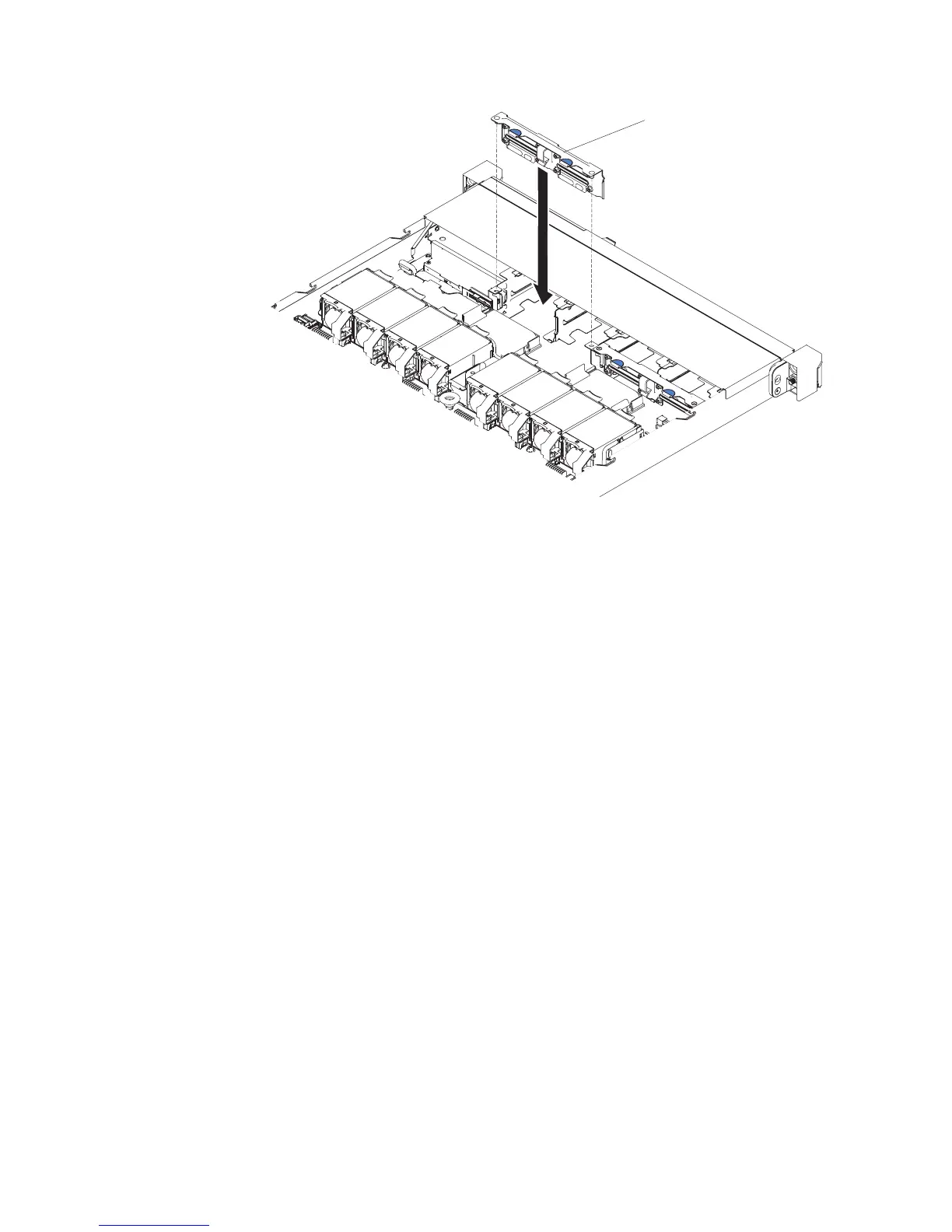
connectors for the 2.5-inch and 3.5-inch backplate assemblies.
4 x 2.5-inch hard disk drive backplate
Figure 130. 4 x 3.5-inch simple-swap hard disk drive backplate assembly installation
Chapter 5. Removing and replacing components 213

 Loading...


