3. Set any jumpers or switches on the drive according to the documentation that
comes with the drive.
4. Remove the filler from the drive cage, if any is present.
5. Attach the drive retention clip that you removed from the previous drive into
the screw holes on the side of the new drive.
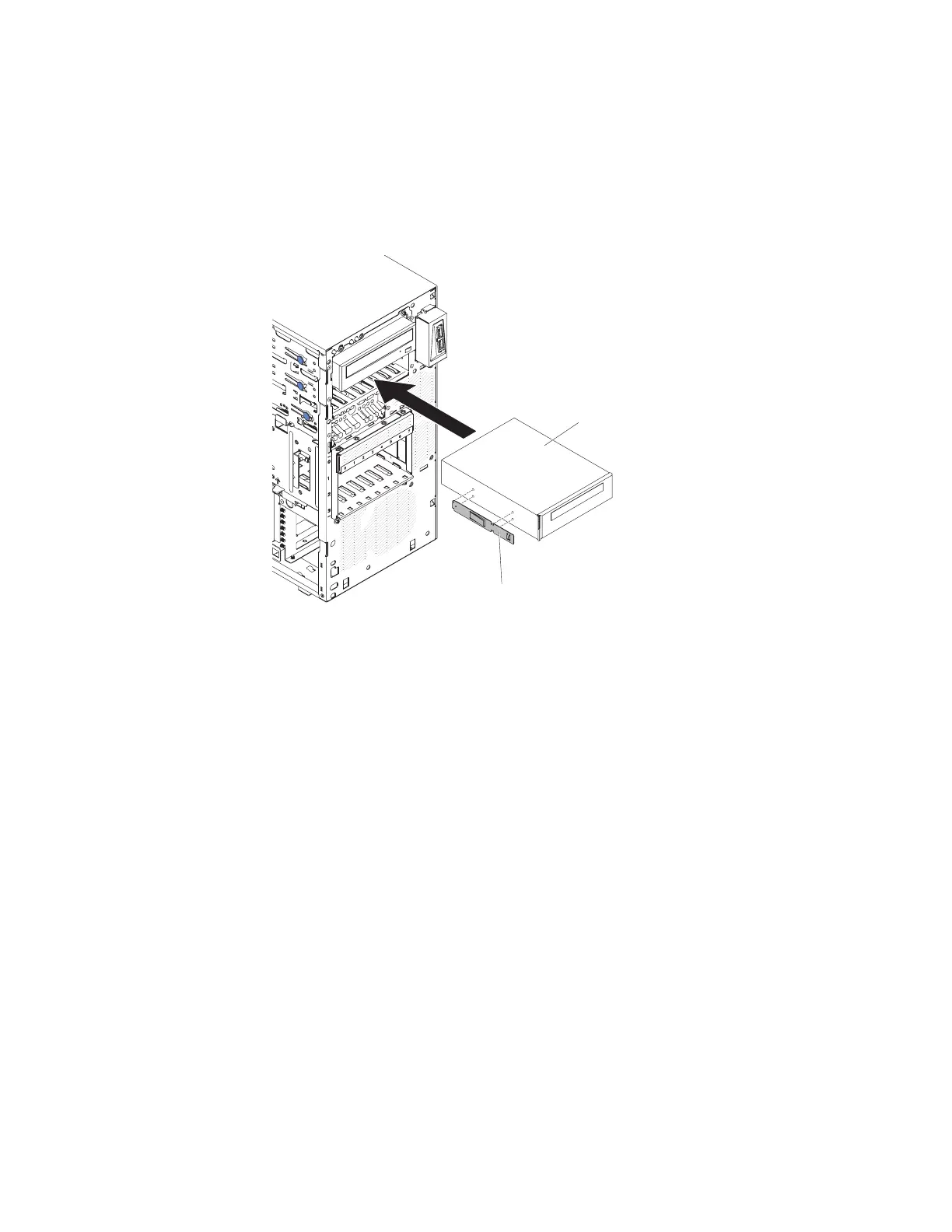
6. Push the drive into the bay.
7. Connect one end of the applicable signal cable into the rear of the drive and
make sure that the other end of this cable is connected into the applicable
connector on the system board.
8. Route the signal cable so that it does not block the airflow to the rear of the
drives or over the microprocessor and dual inline memory modules (DIMMs).
9. Connect the power cable to the rear of the drive. The connectors are keyed
and can be inserted only one way.
10. Install the upper bezel (see “Replacing the upper bezel” on page 192).
11. Install the lower bezel (see “Replacing the lower bezel” on page 190).
12. Install and lock the side cover (see “Replacing the side cover” on page 182).
13. Reconnect the external cables and power cords; then, turn on the attached
devices and turn on the server.
Drive retainer clip
Tape drive
Figure 116. Tape drive installation for 5U server model with hot-swap power supplies
Chapter 6. Removing and replacing components 215

 Loading...


