13. Connect the power cable to the rear of the drive. The connectors are keyed
and can be inserted only one way.
Attention: If no tape drive is installed, it is important to reinstall the filler back to
the bay.
If you have other devices to install, do so now. Otherwise, go to “Completing the
installation” on page 82.
Installing a simple-swap hard disk drive
This procedure applies only to 4U server models with non-hot-swap power
supplies.
The 4U server model with non-hot-swap power supplies supports up to four
3.5-inch simple-swap SATA hard disk drives, which are accessible from the front of
the server.
Note: Only 3TB or below hard disk drive options are supported by the 4U server
model with non-hot-swap power supplies .
You must disconnect all power from the server before you remove or install
simple-swap drives. Before you install a simple-swap SATA hard disk drive, read
the following information:
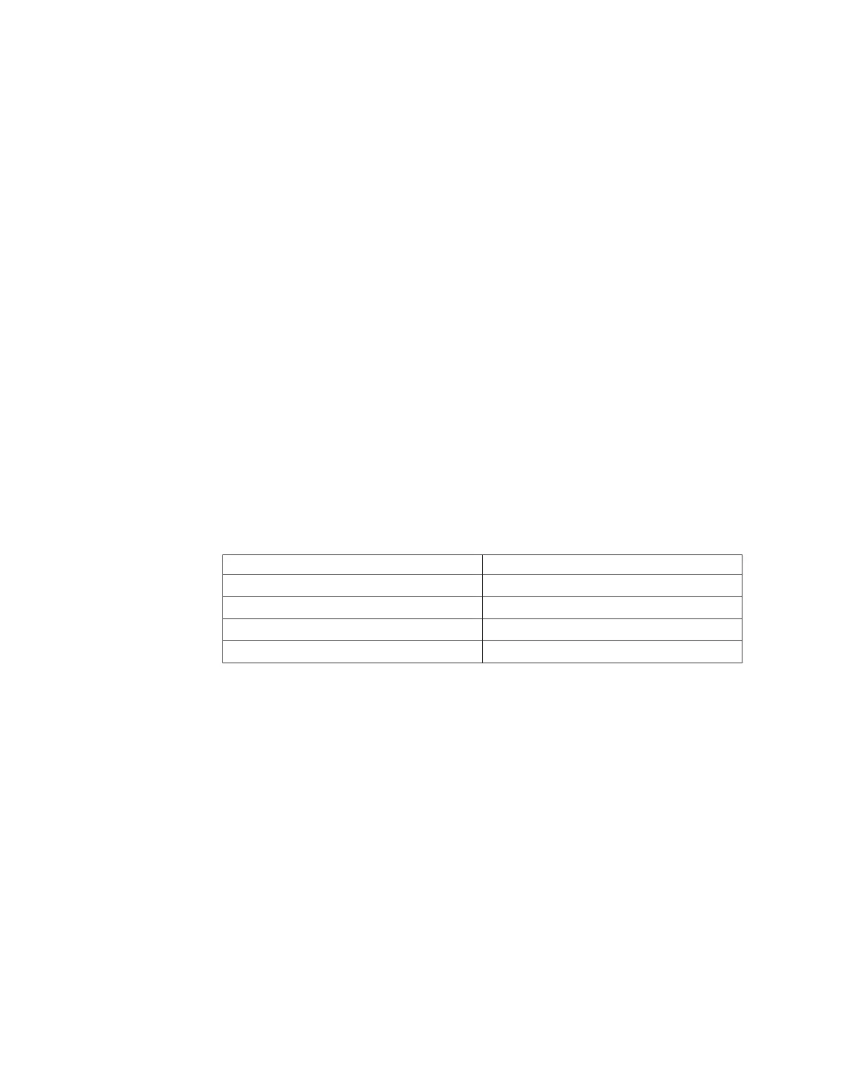
Install the drives starting from the top bay to the bottom bay (bay 3, 4, 5, and then
6). The following tables list the IDs of the hard disk drives:
Table 8. IDs of simple-swap drives
Drive bay HDD ID
30
41
52
63
v The simple-swap SATA hard disk drives connect to the SATA 0 through SATA 3
connectors on the system board as follows:
– System board end cable connector 0 connects to the SATA 0 connector on the
system board.
– System board end cable connector 1 connects to the SATA 1 connector on the
system board.
– System board end cable connector 2 connects to the SATA 2 connector on the
system board.
– System board end cable connector 3 connects to the SATA 3 connector on the
system board.
v
– Hard disk drive 0 connects to the SATA 0 connector on the system board.
– Hard disk drive 1 connects to the SATA 1 connector on the system board.
– Hard disk drive 2 connects to the SATA 2 connector on the system board.
– Hard disk drive 3 connects to the SATA 3 connector on the system board.
Note: Under RAID mode:
1. In uEFI setup menu:
58 System x3100 M5 Type 5457: Installation and Service Guide

 Loading...


