Attention: Static electricity that is released to internal server components when
the server is powered on might cause the server to halt, which might result in the
loss of data. To avoid this potential problem, always use an electrostatic-discharge
wrist strap or other grounding system when you work inside the server with the
power on.
To install a DIMM on 4U server models with non-hot-swap power supplies,
complete the following steps. For the 5U server model with hot-swap power
supplies, please see the next sub-section.
1. Read the safety information in “Safety” on page vii and “Installation
guidelines” on page 35.
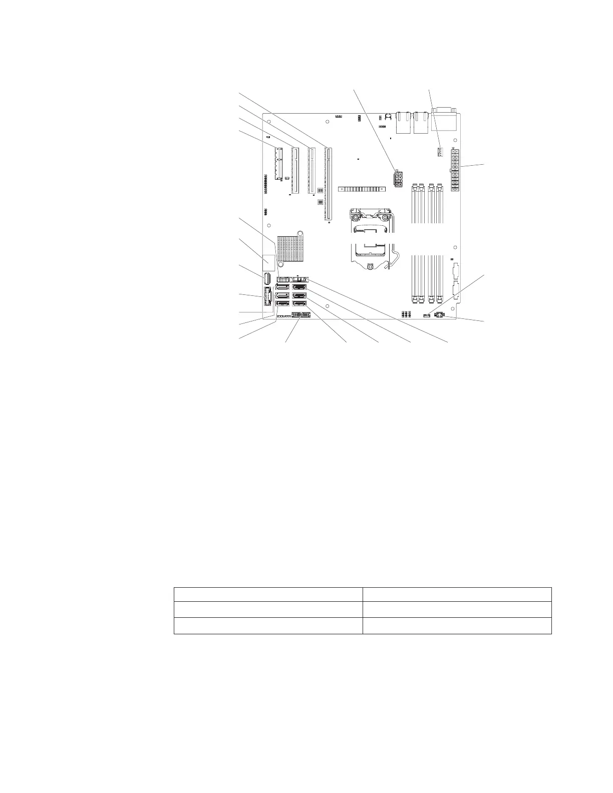
2. Locate the DIMM connectors on the system board. Determine the connectors
into which you will install the DIMMs. Install the DIMMs in the sequence
shown in the following table.
Table 38. DIMM installation sequence
Number of DIMMs Installation sequence (connectors)
First pair of DIMMs 1, 3
Second pair of DIMMs 2, 4
3. Open the retaining clips and, if necessary, remove any existing DIMM.
Attention: To avoid breaking the retaining clips or damaging the DIMM
connectors, open and close the clips gently.
Fan 1 connector
Power supply
connector
Microprocessor
power connector
HDD backplane
power connector
Operator information
panel connector
S ATA 2 S ATA 1 S ATA 0
S ATA 3
S ATA 4
S ATA 5
Front USB
connector
USB tape drive
connector
USB hypervisor
connector
PCI slot 1
PCI slot 2
PCI slot 3
PCI slot 4
Battery
Fan 2 connector
Microprocessor
DIMM 1
DIMM 2
DIMM 3
DIMM 4
Thermal
sensor
connector
Figure 189. DIMM connectors on system board
Chapter 6. Removing and replacing components 277

 Loading...


