holes as shown in the illustration.
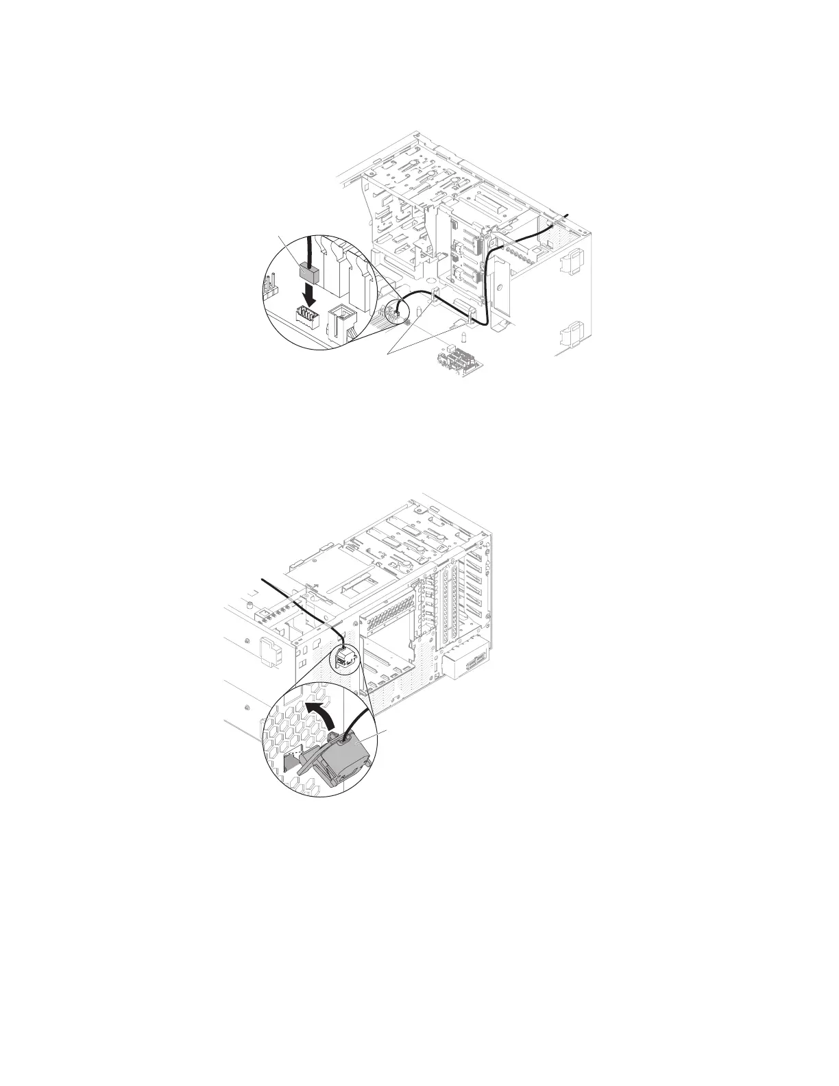
3. Connect the thermal sensor connector to the system board. Remember to close
the cable clips to secure the cable.
4. Stand the server back up in its vertical position.
5. Install the upper bezel (see “Replacing the upper bezel” on page 192).
6. Install the lower bezel (see “Replacing the lower bezel” on page 190).
7. Install and lock the side cover (see “Replacing the side cover” on page 182).
8. Reconnect the external cables and power cords; then, turn on the attached
devices and turn on the server.
Thermal sensor
connector
Cable clips
Figure 208. Thermal sensor board installation for 5U server model with hot-swap power
supplies
Thermal sensor
Figure 209. Installing thermal sensor connector to system board for 5U server model with
non-hot-swap power supplies
294 System x3100 M5 Type 5457: Installation and Service Guide

 Loading...


