The following table describes the functions of switches and jumpers on the system
board.
Table 2. System board switches and jumpers definition
Jumper number Jumper name Jumper setting
J12 Low security jumper
v Pins 1 and 2: Normal (default).
v Pins 2 and 3: Activate low security.
OVR 1 IMM SPI enable jumper
v Pins 1 and 2: Disabled.
v Pins 2 and 3: Enable IMM SPI half
ROM default)
J16 UEFI boot backup jumper
v Pins 1 and 2: Boot from primary
BIOS page (default).
v Pins 2 and 3: Boot from backup
BIOS page.
CLR RTC 1 Clear CMOS jumper
v Pins 1 and 2: Keep CMOS data
(default).
v Pins 2 and 3: Clear CMOS data.
Note:
1. If no jumper is present, the server responds as default.
2. Changing the position of the boot block jumper from pins 1 and 2 to pins 2 and 3 for 5 seconds before the server
is turned on alters which flash ROM page is loaded. Do not change the jumper pin position after the server is
turned on. This can cause an unpredictable problem.
Important:
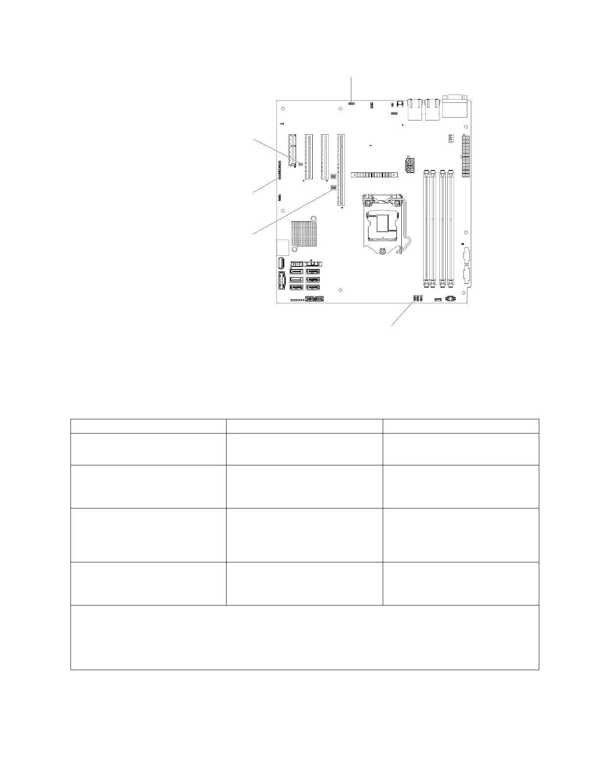
Low security jumper (J12)
IMM SPI enable
jumper (OVR 1)
UEFI boot backup
jumper (J16)
Clear CMOS jumper
(CLR RTC 1)
System TPM physical
jumper (SW1)
Figure 16. Location and description of switches and jumpers
Chapter 2. Installing optional devices 33

 Loading...


