12-2
12
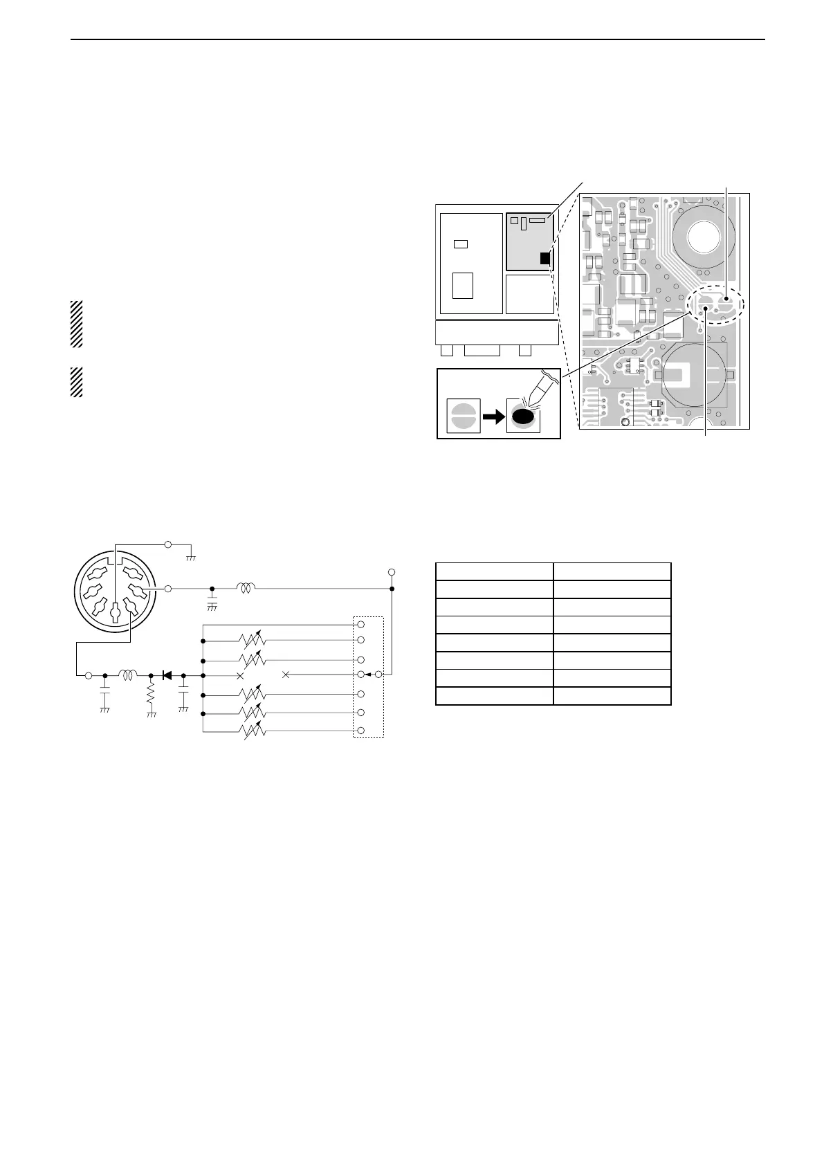
INFORMATION
Band voltage modication ■
If you want to connect an external unit that can be con-
trolled by the band voltage from the [ACC] connector,
the modification is shown to the right.
The band voltage is on pin 5 of [ACC] connector after
modification (q) is completed, or the regulated 8 V is
on pin 1 of [ACC] connector after modification (w) is
completed.
Performing this modification is the customer’s re-
sponsibility. Icom does not guarantee this modifica-
tion’s result.
CAUTION: Disconnect the DC power cable from the
transceiver before working on the transceiver.
Bridge these
solder pads
IC-7200’s bottom view with
bottom cover removed.
RF unit
Front panel
q BAND
w 8 V
• Band voltage generator circuit
The circuit below is just for reference.
1.9 MHz
Rotary
switch
Diode
VR 4.7 kø
4.7 kø
4.7 kø
100 µH
100 µH
4700 pF
4700 pF
4700 pF
BAND
8 V
8 V
External
power souce
ACC socket of
an optional unit
GND
10 kø
10 kø
22 kø
VR
Open
VR
VR
OR
3.5 MHz
7 MHz
10 MHz
14 MHz
18/21 MHz
24/28 MHz
1
2
3
4
7
6
5
The following band voltage table is for reference only.
Please adjust and check with the actual operating re-
sults.
BAND VOLTAGE
1.9 MHz Non-adjustment
3.5 MHz 6.1 V
7 MHz 5.1 V
10 MHz Non-adjustment
14 MHz 4.1 V
18/21 MHz 3.1 V
24/28 MHz 2.1 V

 Loading...


