1-4
1
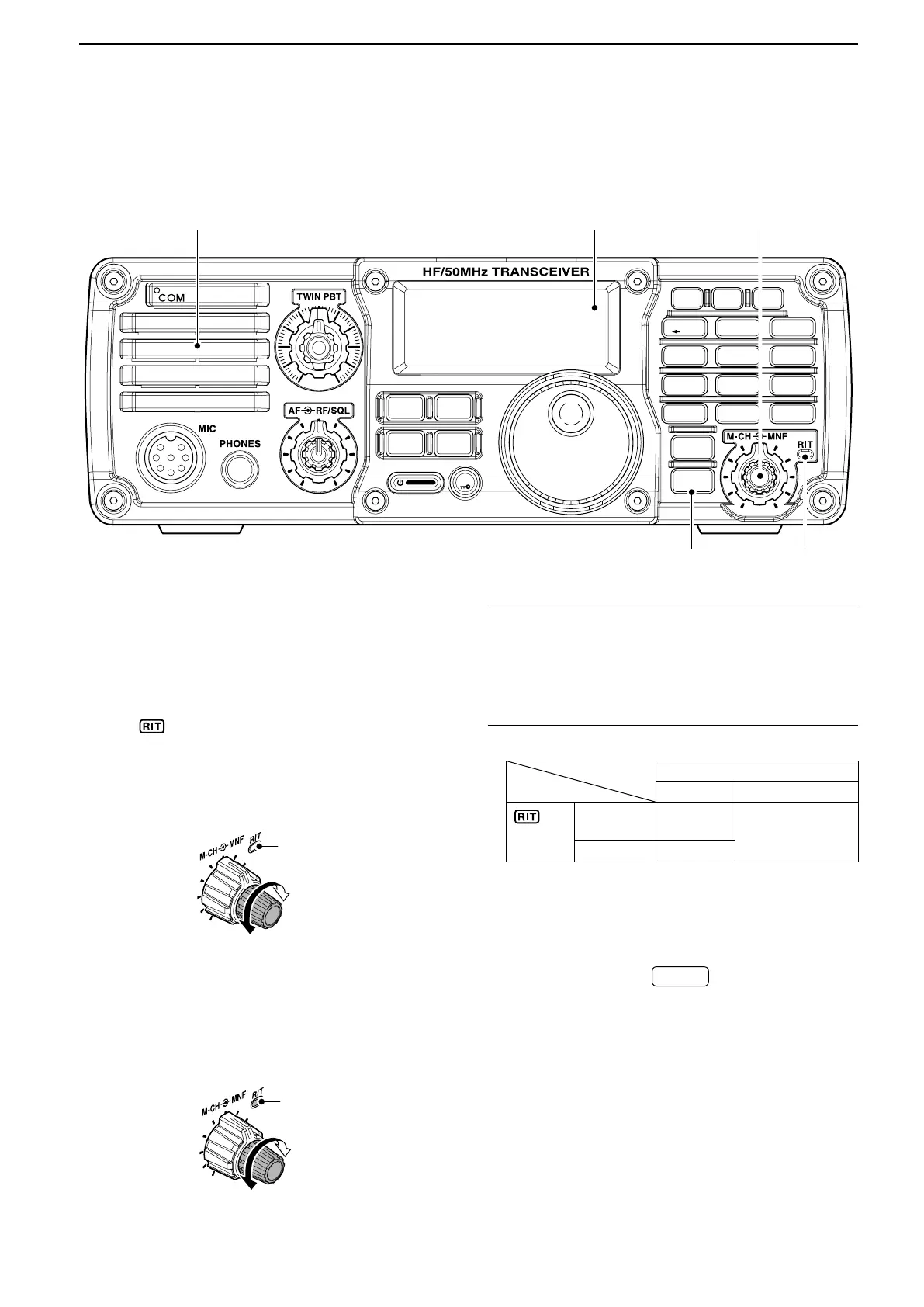
PANEL DESCRIPTION
u M-CH/RIT CONTROL [M-CH] (inner control)
While in the Set mode/Quick Set mode, rotate to ➥
select the Set mode item. (p. 10-2)
This control can be set as the memory channel ➥
control or the RIT control.
• The RIT function should be turned ON rst to activate
this control as the RIT control. (p. 5-2)
- “
” appears when the RIT function is ON.
• The RIT control indicator (i) lights orange when this
control is activated as the RIT control.
When [M-CH] acts as the M-CH control:
Rotate to select a memory channel. (p. 7-2)
OFF
M-CH
Channel decreases
Channel increases
When [M-CH] acts as the RIT control:
Rotate to shift the receive frequency. (p. 5-2)
• Rotate the control clockwise to incerase the frequen-
cy, or rotate the control counterclockwise to decrease
the frequency.
• The shift frequency range is ±9.999 kHz in 1 Hz steps
(or ±9.99 kHz in 10 Hz steps).
Lights orange
RIT
Frequency decreases
Frequency increases
What is the RIT function? ✓
The RIT (Receiver Incremental Tuning) shifts the re-
ceive frequency without shifting the transmit frequency.
This is useful for fine tuning stations calling you off fre-
quency, or when you prefer to listen to slightly different
sounding audio characteristics.
• About the [M-CH] control activation:
RIT control indicator (i as below)
Lights OFF
icon
(!6 on page
1-13)
Appears
Acts as the
RIT control
Acts as the memo-
ry channel control
Disappears N/A
i RIT CONTROL INDICATOR (pp. 5-2, 7-2)
Lights orange when the [M-CH] control (u) is se-
lected as the RIT control.
o M-CH/RIT•SET KEY
M-CH/RIT
SET
Push to toggle the ➥ [M-CH] control between the
memory channel control and the RIT control.
•
The RIT function should be turned ON first.
(p. 5-2)
• The RIT control indicator (y) lights orange when the
[M-CH] control functions as the RIT control.
Hold down for 1 second to enter the Quick Set ➥
mode. (p. 10-2)
In the Quick Set mode, hold down for 1 second to ➥
enter the Set mode (p. 10-3)
In the Quick Set mode or Set mode, push ➥ to re-
turn to normal operation. (p. 10-2, 10-3)
i7200
MODE
TUNER
TS
FILTER
SPCH
V/M
A/B
SPLIT
M-CL
SCAN
SET
ATT
P
.
AMP
COMP
VOX
MNF
RIT
1
23
456
7
8
0
50
28
1814
10
21
24
=
7
3.51.8
F-INP
M-CH/RIT
ENT
BAND
GENE
9
.
AGC
MW
ANF
METER
NRNB
Speaker
Function
Display (p. 1-12)
u
Front panel (Continued) ■

 Loading...


