EasyManua.ls Logo

Icom IC-R8600 - User Manual

Icom IC-R8600
96 pages
Print Icon
To Next Page IconTo Next Page
Loading...
INSTRUCTION MANUAL
iR8600
COMMUNICATIONS RECEIVER

Table of Contents

Other manuals for Icom IC-R8600

Questions and Answers

  • D
    David RiceSep 10, 2025
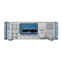
    Why won't my Icom IC-R8600 Receiver programmed scan start?
    • A
      Angela MasonSep 12, 2025
      If your Icom Receiver's programmed scan does not start, it may be because the same frequencies have been set in scan edge memory channels. To resolve this, set different frequencies in scan edge memory channels (P00A/P00B ~ P49A/P49B).
  • K
    Kathleen RossSep 12, 2025
    What to do if Icom Receiver displays '- No File -' when selecting firmware?
    • W
      wcarrilloSep 12, 2025
      If, when selecting a firmware file on your Icom Receiver, "- No File -" is displayed: * Copy the firmware file to the SD card. * Format the SD card with the built-in format function if it is not formatted. * Download the firmware again if the firmware file name has been changed.
  • E
    Eric CalderonSep 13, 2025
    Why is the FSK (RTTY) signal not demodulated on my Icom IC-R8600 Receiver?
    • M
      Marcus ButlerSep 14, 2025
      If the FSK (RTTY) signal is not demodulated on your Icom Receiver, set the appropriate Mark and Space frequencies, as the Mark or Space frequency may be incorrect.
  • J
    Jeremy JacobsSep 16, 2025
    Why is FSK signal received but not decoded on Icom Receiver?
    • P
      peterbaileySep 16, 2025
      If the FSK (RTTY) signal is received but not decoded on your Icom Receiver, select the FSK-R (Reverse) mode, as the shift setting may be reversed.

Summary

Features

Panel Description

Front Panel Controls

Describes the keys, dials, and indicators on the receiver's front panel.

Panel Description (Continued)

Rear Panel Connectors

Details the various input and output ports on the receiver's rear panel.

Touch Panel Display Indicators

Explains the indicators and icons shown on the receiver's touch screen.

Installation and Connections

Grounding and Power Supply Connection

Details safety grounding procedures and power connection steps.

Connecting an Antenna

Instructions for connecting antennas to the receiver.

Installation and Connections (Continued)

External Device Connections

Describes connecting headphones, speakers, PCs, and other peripherals.

Basic Operation

Mode Selection and Frequency Setting

Explains how to change receive modes and set frequencies.

Basic Operation (Continued)

Frequency Setting Methods

Details direct frequency entry and dial rotation for tuning.

Dial and Panel Lock Functions

Explains how to lock controls to prevent accidental changes.

Scope Operation

Using the Spectrum Scope

Guide to activating and navigating the spectrum scope interface for signal analysis.

Scope Operation (Continued)

Setting Spectrum Scope Span and Range

Adjusting the frequency range and display span for the spectrum scope.

Peak Signal Search and Touch Operation

Finding strongest signals and using touch gestures for tuning.

Adjusting Reference Level and Sweep Speed

Fine-tuning signal visibility and refresh rate on the scope.

Scope Set Screen Configuration

Customizing scope parameters like display type, colors, and averaging.

Other Functions

Antenna Selection and AGC Control

Covers selecting antennas and managing automatic gain control.

Other Functions (Continued)

IP Plus Function and Notch Filter

Enhancing signal quality and suppressing interference with specific filters.

Digital IF Filter Selection and Adjustment

Choosing and configuring digital IF filters for different modes.

Noise Blanker and Noise Reduction

Using features to eliminate pulse noise and reduce random noise.

Viewing FSK Log Contents and Tone;Shift Settings

Accessing saved logs and adjusting FSK signal parameters.

Digital Twin PBT Operation

Using passband tuning filters for precise interference rejection.

Filter Shape Selection

Selecting between SHARP and SOFT filter shapes for optimal audio.

Receiving FSK (RTTY) Signals

Procedures for receiving and decoding FSK signals.

Recording and Playing Back

Recording and Playing Back (Continued)

Using an SD Card

Using an SD Card (Continued)

Memory Operation

Memory Operation (Continued)

Writing Memory Channels

Saving current frequency and settings to memory.

SCANS

SCANS (Continued)

Clock and Timer

Clock and Timer (Continued)

SET MODE

SET MODE (Continued)

Connector Configuration Options

Detailed settings for all external connections.

Firmware Update and Other Settings

Procedures for updating firmware and accessing miscellaneous settings.

MAINTENANCE

MAINTENANCE (Continued)

Receiver Resetting Procedures

How to perform partial and full resets.

Touch Screen Calibration

Calibrating the touch screen for accurate operation.

Troubleshooting Common Problems

A guide to diagnosing and resolving operational issues.

UPDATING THE FIRMWARE

UPDATING THE FIRMWARE (Continued)

Performing the Firmware Update

Step-by-step instructions for updating the receiver's firmware.

SPECIFICATIONS

CONNECTOR INFORMATION

Detailed Connector Descriptions

Explains the function and specifications of each connector.

Icom IC-R8600 Specifications

General IconGeneral
Frequency Coverage0.01–3000 MHz
Receiver TypeSuperheterodyne
ModesAM, FM, WFM, CW
Display4.3 inch color TFT LCD
Antenna ConnectorSO-239 (50 Ω)
Power Supply13.8 V DC ±15%
Image Rejection RatioMore than 70 dB
Dynamic RangeMore than 100 dB
Current Consumption1.5 A (max)

Related product manuals