v
List of Figures
Figure 1-1: Contents of Package...................................................................................1-2
Figure 1-2: Self Test In Progress..................................................................................1-3
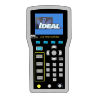
Figure 2-1: Display Handset (DH)................................................................................2-6
Figure 2-2: LCD Ready Screen.....................................................................................2-8
Figure 2-3: Display Handset Interface Ports................................................................2-13
Figure 2-4: PCMCIA Slots.........................................................................................2-14
Figure 2-5: PCMCIA Adapter, Compact Flash Card and Reader.................................2-14
Figure 2-6: Remote Handset (RH)..............................................................................2-15
Figure 2-7: Remote Handset Interface Ports...............................................................2-17
Figure 2-8: Tester AC/DC Wall Cube Adapter ...........................................................2-19
Figure 3-1: Loss Components of a Total Link...............................................................3-5
Figure 3-2: Sample Warning Screen .............................................................................3-7
Figure 3-3: Tester Field Calibration Setup ....................................................................3-8
Figure 3-4: Custom Cable Parameter Screen...............................................................3-38
Figure 3-5: Typical Tone Generator Setup..................................................................3-39
Figure 3-6: TDR Graphical Plot Layout and Controls.................................................3-47
Figure 4-1: Tabular Data and Graphical Plot Layout...................................................4-22
Figure 6-1: Typical Installation Window.......................................................................6-3
Figure 6-2: PC Uploading Cable Pinout........................................................................6-5
Figure 6-3: PC to Tester Connections...........................................................................6-6
Figure 7-1: Twisted Pair Cables....................................................................................7-2
Figure 7-2: Shield Continuity Test Connections Twisted Pair........................................7-3
Figure 7-3: Permanent Link Test Connections ..............................................................7-4
Figure 7-4: Channel Link Test Connections..................................................................7-5
Figure 7-5: 10BASE-T Connector..............................................................................7-31

 Loading...