Chapter 3
Calibration, Configuration, and Special Operations
3-5
Design Overview
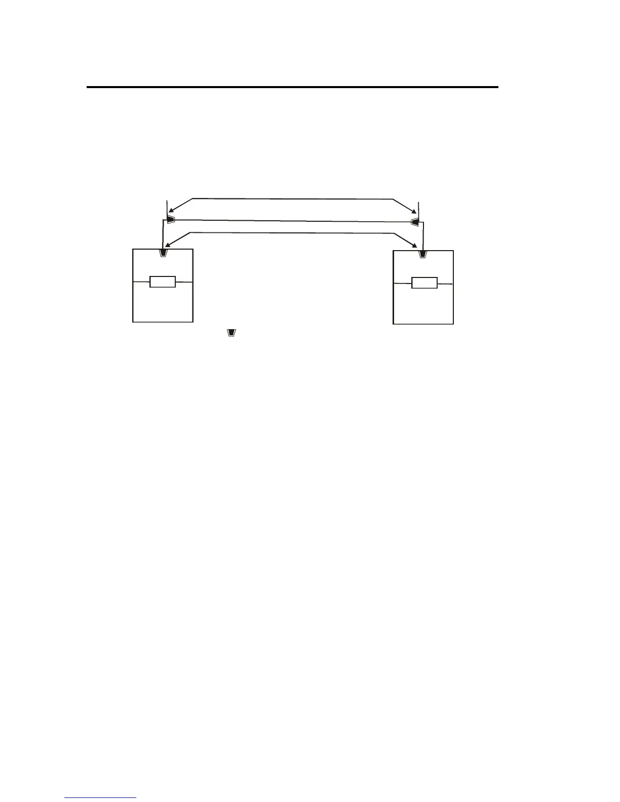
The test lead to the adapter is a mated pair connection rather than a soldered
connection. Allowing the use of the same adapter for both Permanent Link and
Channel Link testing. The overall loss measurement is shown in Figure 3-1.
Horizontal Cable
Channel
Adapter
Tester
Remote End
Display End
Adapter
Tester
TAI
TAI
TAI - Tester Adapter Interface
Mated Plug Jack Pair
Figure 3-1: Loss Components of a Total Link
All of the loss effects of each of the above components must be known in order to
properly report the Loss Effects of a Permanent Link or a Channel Link.
• Channel losses can be measured when the background loss effects of the test
units, adapters, and the test unit/adapter interfaces are subtracted from the
measured overall raw loss effects.
• Permanent link losses are measured when the loss effects of the test lead
patchcords and the mated pair making up the adapter/patchcord interface are
subtracted from the overall Channel losses.

 Loading...