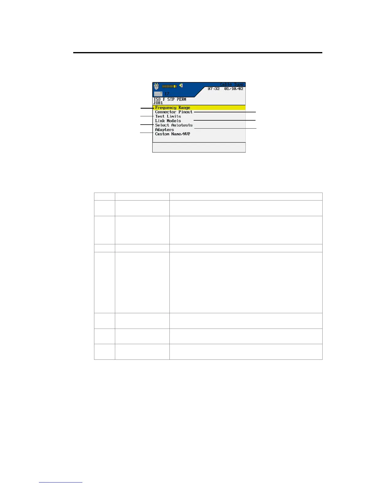
Figure 3-4: Custom Cable Parameter Screen
Table 3-5: Custom Cable Parameter Options
Item Parameter Description
1 Frequency Range Use this menu to set minimum and maximum certification
and cable grade frequencies.
2 Connector Pinout This screen is used to define connector pinouts.
Note: If one wire pair is not selected, tests for NEXT,
attenuation, capacitance, DC resistance, and
impedance will not be performed on that pair.
3 Test Limits This screen is used to customize Autotest pass/fail limits.
4 Link Models Custom NEXT and Attenuation limits are set by using a
flat line limit or one of several different models.
Frequency limits will vary from less than 1 to 350 MHz
for the LANTEK 6 and from 1 to 750 MHz for the
LANTEK 7 based on the link type.
For a detailed description of the methods and limits for
calculating NEXT and Attenuation values, refer to
Appendix C, Measurement Methods and Limits.
5 Select Autotests Not all cables will require the full suite of Autotests. Use
this menu to select the Autotests to be performed.
6 Adapters Use this menu to indicate which near-end and far-end
cable adapters are currently being used.
7 Custom
Name/NVP
Use the alphanumeric keys to enter a custom name or
change the NVP parameters. The LANTEK testers can
 Loading...