FC6A S
ERIES
MICROS
MART
L
ADDER
P
ROGRAMMING
M
ANUAL
FC9Y-B1726 18-9
18: P
ULSE
O
UTPUT
I
NSTRUCTIONS
Settings
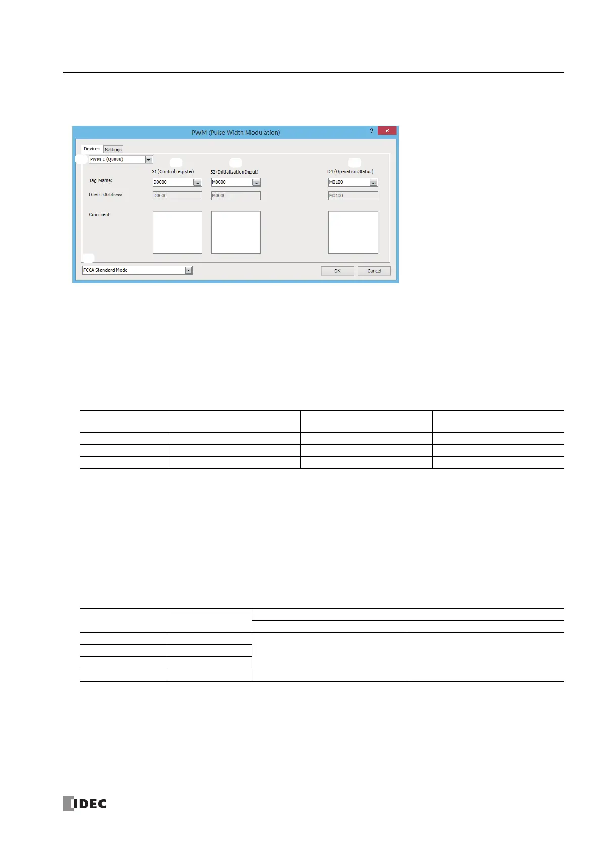
■ Devices tab
1. Select Mode
Selects the configuration mode. FC6A Standard Mode, FC4A Compatible Mode, FC5A (except FC5A-D12X1E)
Compatible Mode, or FC5A-D12X1E Compatible Mode can be selected.
To use the PWM instruction with the FC4A Series MICROSmart, the FC5A Series MICROSmart, or the FC5A-D12 PWM instruction
specification, select one of the FC compatibility modes. When changing the PLC type from the FC4A Series MICROSmart, FC4A
Compatible Mode is automatically selected. When changing the PLC type from the FC5A or FC5A-D12, FC5A (except FC5A-
D12X1E) Compatible Mode or FC5A-D12X1E Compatible Mode is automatically selected.
The frequency that can be specified in FC compatibility mode is an approximate value of the FC4A, FC5A, and FC5A-D12 PWM
instruction frequencies.
Note: The pulse frequencies that can be output in FC compatibility mode are as follows.
The rest of this section is written under the assumption that FC6A Standard Mode has been selected.
Notes:
• For details on the FC4A Compatible Mode settings, refer to the PWM instruction in Chapter 2 "Instructions" in the "FC4A Series MICROSmart
User's Manual".
• For details on the settings in FC5A (except FC5A-D12X1E) Compatible Mode and FC5A-D12X1E Compatible Mode, refer to the PWM
instruction in Chapter 13 "Pulse Instructions" in the FC5A Series MICROSmart Pentra User's Manual Advanced Volume.
2. Select instruction
This item selects which PWM instruction to use ("PWM1", "PWM2", "PWM3", or "PWM4").
The pulse output that can be set is determined by the instruction and the CPU module type.
All-in-One CPU module
*1 When the output is Q0 or Q1 and the calculated OFF time is shorter than 15 μs, the pulse duty cycle is adjusted so that the OFF time becomes
15 μs, and then the pulse is output.
*2 When the output is Q2 or Q3, configure the output pulse frequency and pulse duty cycle so that ON time and OFF time are greater than or equal
to 100 μs.
*3 For details on the output delay time of each output, see Chapter 2 "Product Specifications" in the "FC6A Series MICROSmart User's Manual".
Operation Mode FC4A Compatible Mode
FC5A (except FC5A-D12X1E)
Compatible Mode
FC5A-D12X1E Compatible Mode
Operation mode 0 15 Hz (fixed) 15 Hz (fixed) 15 Hz (fixed)
Operation mode 1 27 Hz (fixed) 46 Hz (fixed) 61 Hz (fixed)
Operation mode 2 218 Hz (fixed) 366 Hz (fixed) 488 Hz (fixed)
Instruction Pulse Output
Configurable Range
Frequency Duty Cycle
PWM1 Q0
*1*3
15 Hz to 5 kHz (increments of 1 Hz) 0.1 to 100.0 (increments of 0.1%)
PWM2 Q1
*1*3
PWM3 Q2
*2*3
PWM4 Q3
*2*3
1.
2.
3. 4. 5.

 Loading...