18: P
ULSE
O
UTPUT
I
NSTRUCTIONS
18-10 FC6A S
ERIES
MICROS
MART
L
ADDER
P
ROGRAMMING
M
ANUAL
FC9Y-B1726
CAN J1939 All-in-One CPU module/Plus CPU module
*1 When the output is Q0 or Q1 and the calculated OFF time is shorter than 15 μs, the pulse duty cycle is adjusted so that the OFF time becomes
15 μs, and then the pulse is output.
*2 For details on the output delay time of each output, see Chapter 2 "Product Specifications" in the "FC6A Series MICROSmart User's Manual".
3. S1 (source 1): Control register
S1 specifies the first data register of the data registers to use with PWM1, PWM2, PWM3, or PWM4 instructions.
Starting from the specified data register, 8 consecutive data registers are used.
Specify the first data register so that the device range is not exceeded.
*1 The upper and lower data registers change according to the 32-bit data storage method specified.
For details, see "32-bit Data Storage" on page 3-9.
4. S2 (source 2): Initialization Input
S2 specifies the initialization input. When the initialization input S2 is turned on, the initial values configured in the WindLDR
PWM (Pulse Width Modulation) dialog box, on the Settings tab, are stored in the control registers. An external input or an
internal relay can be specified.
When the initialization input is on, the initial values are written to the data registers with each scan. To only initialize the values
one time, use the initialization input in combination with the SOTU (single output up) instruction or the SOTD (single output
down) instruction.
5. D1 (destination 1): Operation Status
D1 specifies the first internal relay of the internal relays to use with PWM instructions.
Starting from the specified internal relay, 3 sequential internal relays are used.
Specify the first internal relay so that the device range is not exceeded.
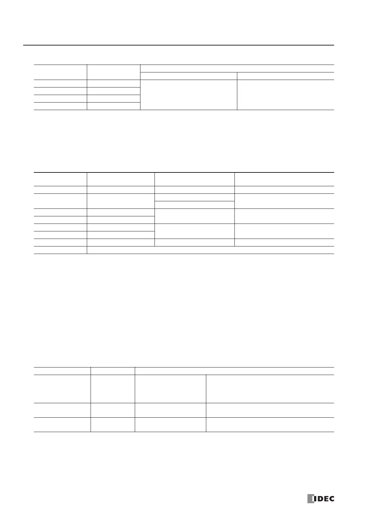
Instruction Pulse Output
Configurable Range
Frequency Duty Cycle
PWM1 Q0
*1*2
15 Hz to 5 kHz (increments of 1 Hz) 0.1 to 100.0 (increments of 0.1%)
PWM2 Q2
*1*2
PWM3 Q4
*1*2
PWM4 Q6
*1*2
Storage
Destination
Function Setting Reference
Starting number+0 Output pulse frequency 15 to 5,000 (increments of 1 Hz) "6. Output pulse frequency" on page 18-11
Starting number+1 Pulse duty cycle (ON ratio)
1 to 1,000 (increments of 0.1%)
"7. Pulse width ratio" on page 18-11
1 to 100 (increments of 1%)
Starting number+2 Preset value (high word)
*1
1 to 100,000,000 pulses "9. Preset value" on page 18-11
Starting number+3 Preset value (low word)
*1
Starting number+4 Current value (high word)
*1
1 to 100,000,000 pulses "10. Current value" on page 18-11
Starting number+5 Current value (low word)
*1
Starting number+6 Error status 0 to 4 "11. Error status" on page 18-11
Starting number+7 Reserved
Storage Destination Function Setting
Starting number+0 Pulse output ON
0: Pulse output OFF
1: Pulse output ON
This relay turns on during pulse output.
This relay turns off when pulse output stops.
This relay turns off when the specified number of pulses
are output and output ends.
Starting number+1
Pulse output
complete
0: Pulse output not complete
1: Pulse output complete
This relay turns on when pulse output is complete.
This relay turns off when pulse output stops.
Starting number+2 Overflow
0: None
1: An overflow has occurred
When pulse counting is enabled, this relay turns on when
a pulse is output that exceeds the configured preset value.

 Loading...