FC6A S
ERIES
MICROS
MART
L
ADDER
P
ROGRAMMING
M
ANUAL
FC9Y-B1726 18-29
18: P
ULSE
O
UTPUT
I
NSTRUCTIONS
(3) S2 (source 2): Initialization input
S2 specifies the initialization input.
When the initialization input is turned on, the initial values configured in the WindLDR RAMPL (Ramp Pulse Output with
Liner Interpolation) dialog box, on the Common Settings tab, are stored in the control registers. An external input or
an internal relay can be specified.
When the initialization input is on, the initial values are stored in the data registers with each scan. (Even when the RAMPL
instruction is not executed (when not on), if the initialization input is turned on, the initial values are stored in the data
registers.) To only initialize the values one time, use the initialization input in combination with the SOTU (single output up)
instruction or the SOTD (single output down) instruction.
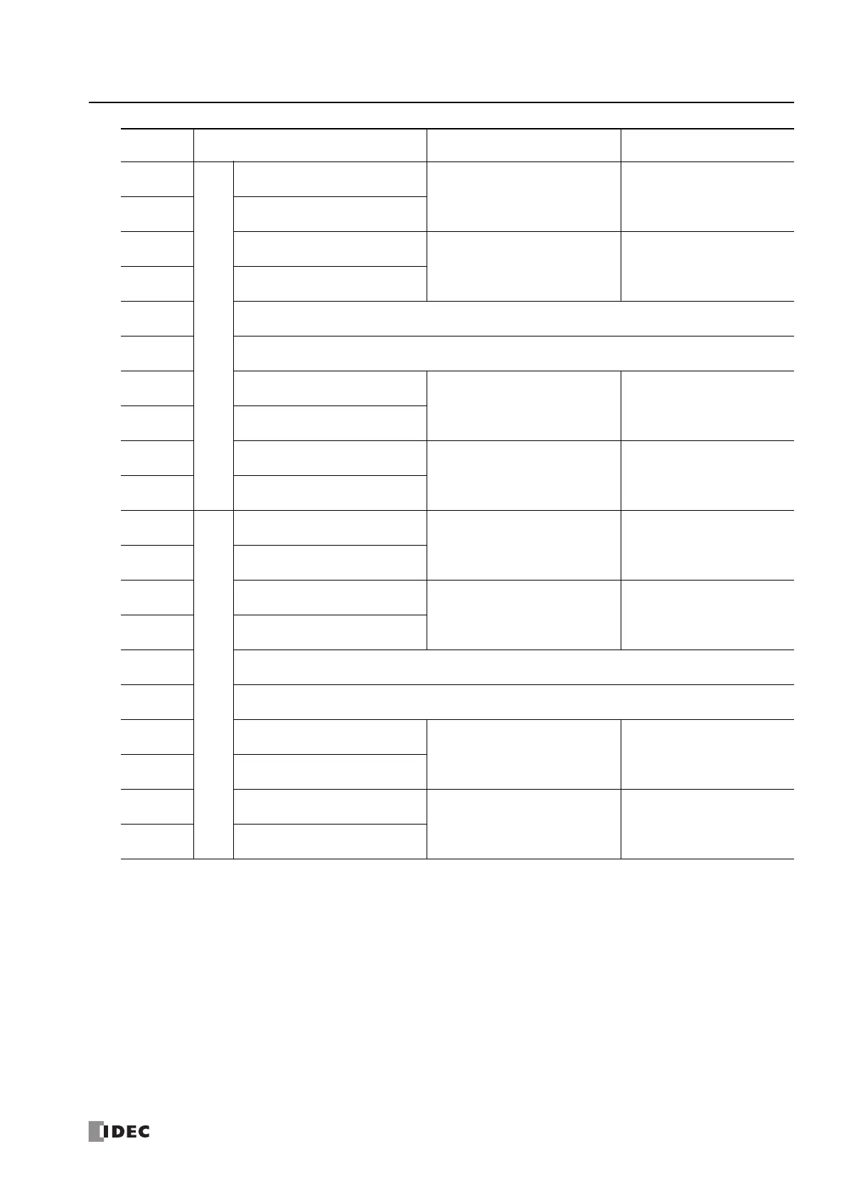
Starting
number+10
X axis
Steady pulse frequency (high word)
*1*2
15 to 100,000 (increments of 1 Hz)
"(9) Steady pulse frequency" on
page 18-32
Starting
number+11
Steady pulse frequency (low word)
*1*2
Starting
number+12
Initial pulse frequency (high word)
*1*2
15 to 100,000 (increments of 1 Hz)
"(10) Initial pulse frequency" on
page 18-32
Starting
number+13
Initial pulse frequency (low word)
*1*2
Starting
number+14
— Reserved —
Starting
number+15
— Reserved —
Starting
number+16
Preset value (high word)
*1
Specify absolute position mode
-2,147,483,648 to 2,147,483,647
pulses
"(13) Preset value" on page 18-33
Starting
number+17
Preset value (low word)
*1
Starting
number+18
Current value (high word)
*1
1 to 100,000,000 pulses
*3
"(14) Current value" on page 18-33
Starting
number+19
Current value (low word)
*1
Starting
number+20
X axis
Steady pulse frequency (high word)
*1*2
15 to 100,000 (increments of 1 Hz)
Starting
number+21
Steady pulse frequency (low word)
*1*2
Starting
number+22
Initial pulse frequency (high word)
*1*2
15 to 100,000 (increments of 1 Hz)
Starting
number+23
Initial pulse frequency (low word)
*1*2
Starting
number+24
— Reserved —
Starting
number+25
— Reserved —
Starting
number+26
Preset value (high word)
*1
Specify absolute position mode
-2,147,483,648 to 2,147,483,647
pulses
"(13) Preset value" on page 18-33
Starting
number+27
Preset value (low word)
*1
Starting
number+28
Current value (high word)
*1
1 to 100,000,000 pulses
*3
"(14) Current value" on page 18-33
Starting
number+29
Current value (low word)
*1
*1 The upper and lower data registers change according to the 32-bit data storage method specified. For details, see "32-bit Data
Storage" on page 3-9.
*2 When the instruction input is turned on, the automatically calculated values are stored in the registers.
*3 The number of output pulses is stored in the data registers, regardless of the value of the absolute position counter.
Storage
Destination
Function Setting Reference

 Loading...