18: P
ULSE
O
UTPUT
I
NSTRUCTIONS
18-76 FC6A S
ERIES
MICROS
MART
L
ADDER
P
ROGRAMMING
M
ANUAL
FC9Y-B1726
11. Control direction
When reversible control is enabled, store 0 in this data register for forward operation and store 1 in this data register for reverse
operation.
12. Current value
The number of pulses outputs is stored in the data registers.
The current value is updated when the JOG instruction is executed at each scan.
When starting pulse output, the current value is reset.
13. Error status
Outputs the error code that corresponds to the content of an error when there is an error in the settings. If a configuration error
occurs when a step starts running, a user program execution error will occur, and error code 20 is stored in D8006.
Error Code List
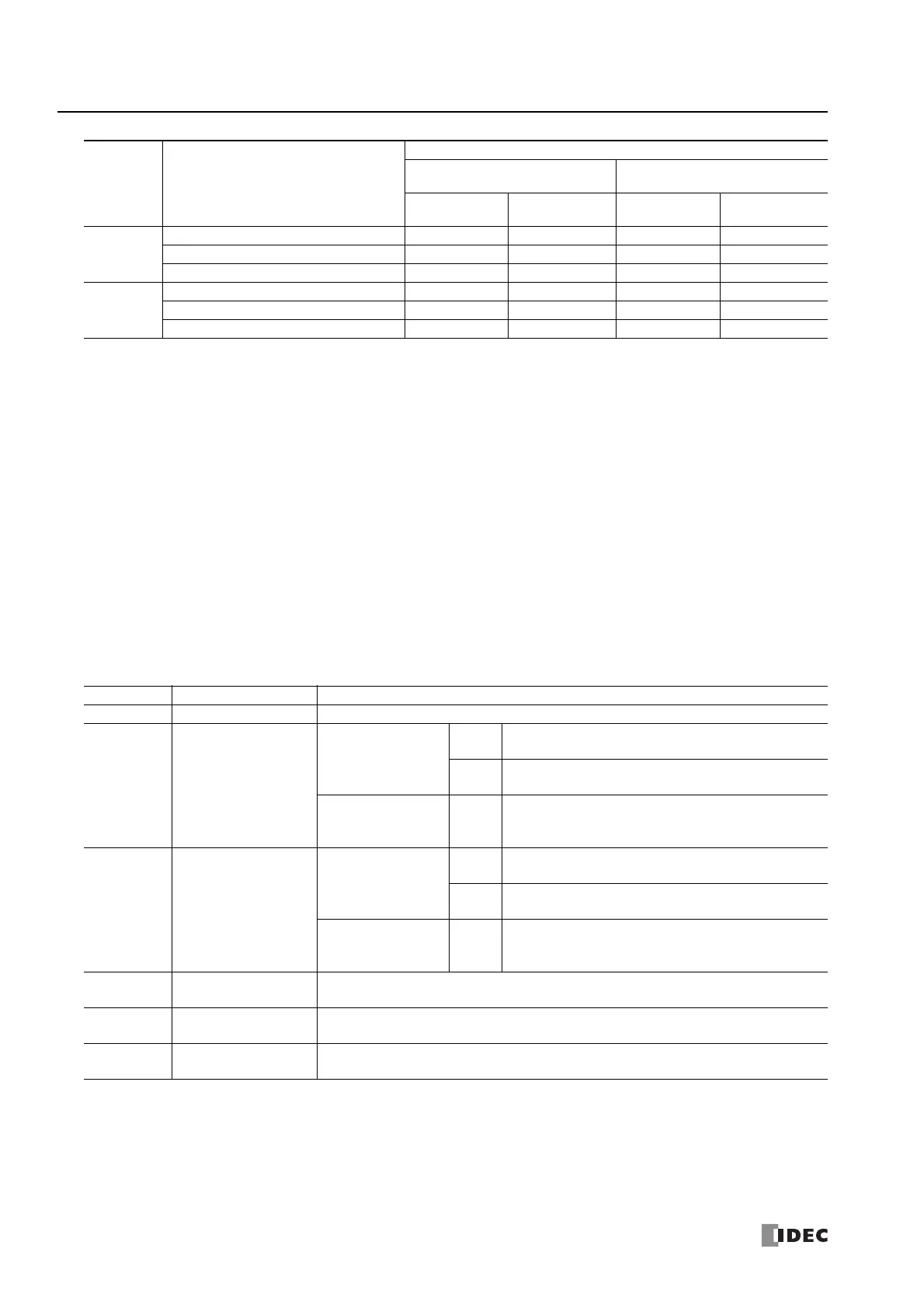
JOG3
Reversible control disabled Q2 — Q4 —
Reversible control Single-pulse output — — Q4 Q5
Reversible control Dual-pulse output ——Q4, Q5—
JOG4
Reversible control disabled Q3 — Q6 —
Reversible control Single-pulse output — — Q6 Q7
Reversible control Dual-pulse output ——Q6, Q7—
*1 When using single-pulse output mode with the All-in-One CPU module, Q2 or Q3 will be used, so an instruction that uses the same output
cannot be used.
*2 When using dual-pulse output mode with the All-in-One CPU module, Q1 will be used, so an instruction that uses the same output cannot be
used.
Error Code Status Description
0Normal —
2
Initial pulse frequency
designation error
All-in-One CPU
module
JOG1,
JOG2
The initial pulse frequency was not set between 15 and
100,000.
JOG3,
JOG4
The initial pulse frequency was not set between 15 and
5,000.
CAN J1939 All-in-One
CPU module/Plus CPU
module
JOG1
to
JOG4
The initial pulse frequency was not set between 15 and
100,000.
4
Steady pulse frequency
designation error
All-in-One CPU
module
JOG1,
JOG2
The steady pulse frequency was not set between 15 and
100,000.
JOG3,
JOG4
The steady pulse frequency was not set between 15 and
5,000.
CAN J1939 All-in-One
CPU module/Plus CPU
module
JOG1
to
JOG4
The steady pulse frequency was not set between 15 and
100,000.
5
Frequency change time
designation error
The acceleration time was not set between 10 and 10,000.
7
Control direction
designation error
The control direction was not set to 0 or 1.
9
Pulse frequency
designation error
The initial pulse frequency was set to the same frequency as the steady pulse frequency or it
was set to a value larger than the steady pulse frequency.
*1
*1 Set the initial pulse frequency so that it is lower than the steady pulse frequency.
Command Operating Condition
Output Used
All-in-One CPU Module
CAN J1939 All-in-One CPU
Module/Plus CPU Module
Pulse Output
Reversible
Control Output
Pulse Output
Reversible
Control Output

 Loading...