FC6A S
ERIES
MICROS
MART
L
ADDER
P
ROGRAMMING
M
ANUAL
FC9Y-B1726 19-53
19: PID C
ONTROL
I
NSTRUCTION
PID instruction dialog box configuration procedure
Use the default value for settings that are not described in this procedure.
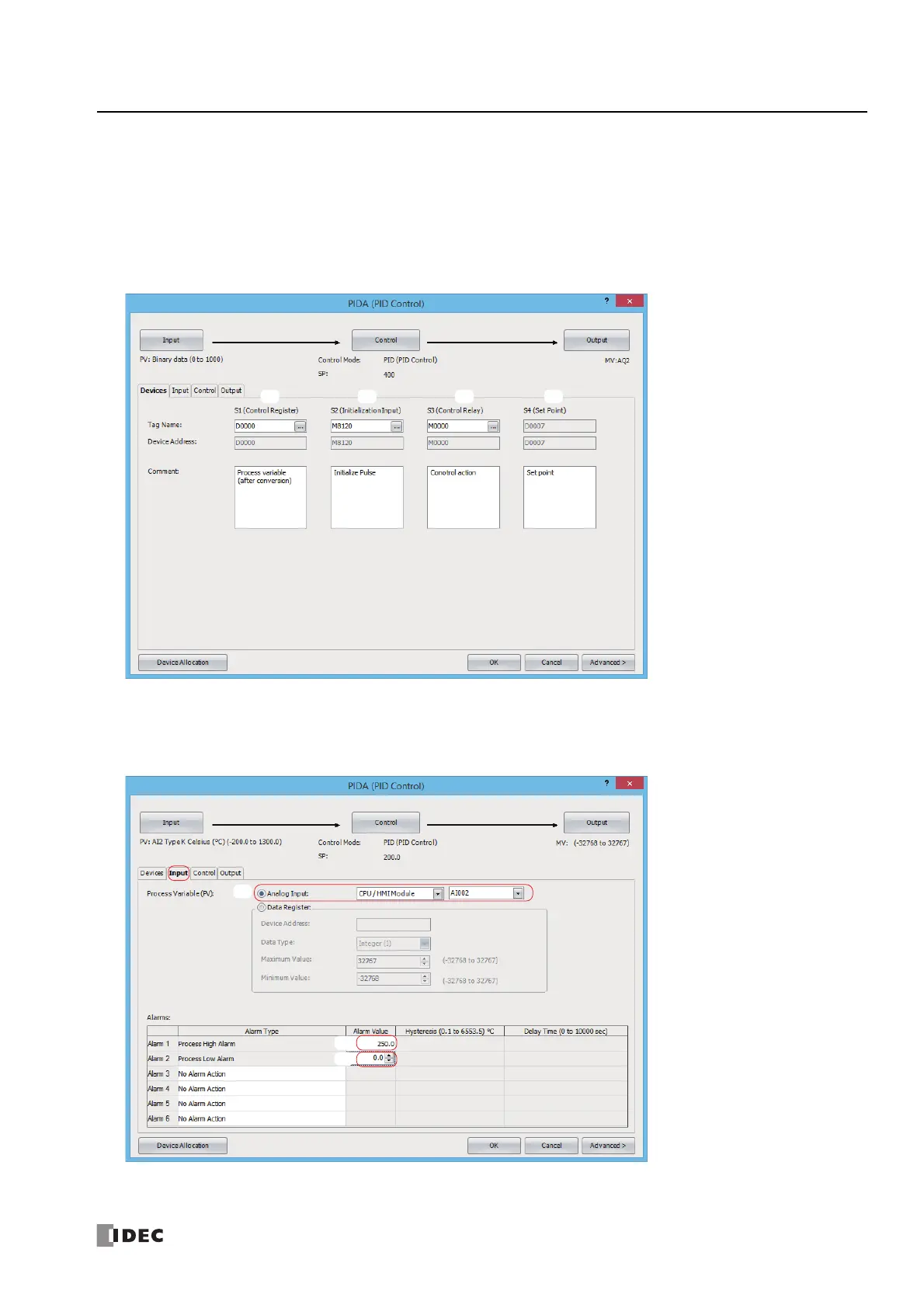
1. The Devices tab configures the devices used with the PID instruction.
• Set S1 (Control Register) to D0000 (1).
• Set S2 (Initialization Input) to M8120 (2).
• Set S3 (Control Relay) to M0000 (3).
• S4 (Set Point) is automatically set to D0007 (4).
2.
Click the Input tab and configure the items.
• For Process Variable (PV), select Analog Input, and then select AI002 (1).
• For Alarm 1, set the alarm value for the process high alarm to 250.0 (2).
For Alarm 2, set the alarm value for the process low alarm to 0.0 (3).

 Loading...