27: F
LOW
C
ALCULATION
I
NSTRUCTIONS
27-6 FC6A S
ERIES
MICROS
MART
L
ADDER
P
ROGRAMMING
M
ANUAL
FC9Y-B1726
(4) D1 (Destination 1): Output Register
Specify the data register that will store the output value, the output value (dead band), and the amount of output change.
6 continuous words are used starting from the specified data register.
(5) D2 (Destination 2): Output Relay
Specify the output or internal relay to store the output value (dead band) change notification and the input value alarm
output. 2 continuous words are used starting from the specified device.
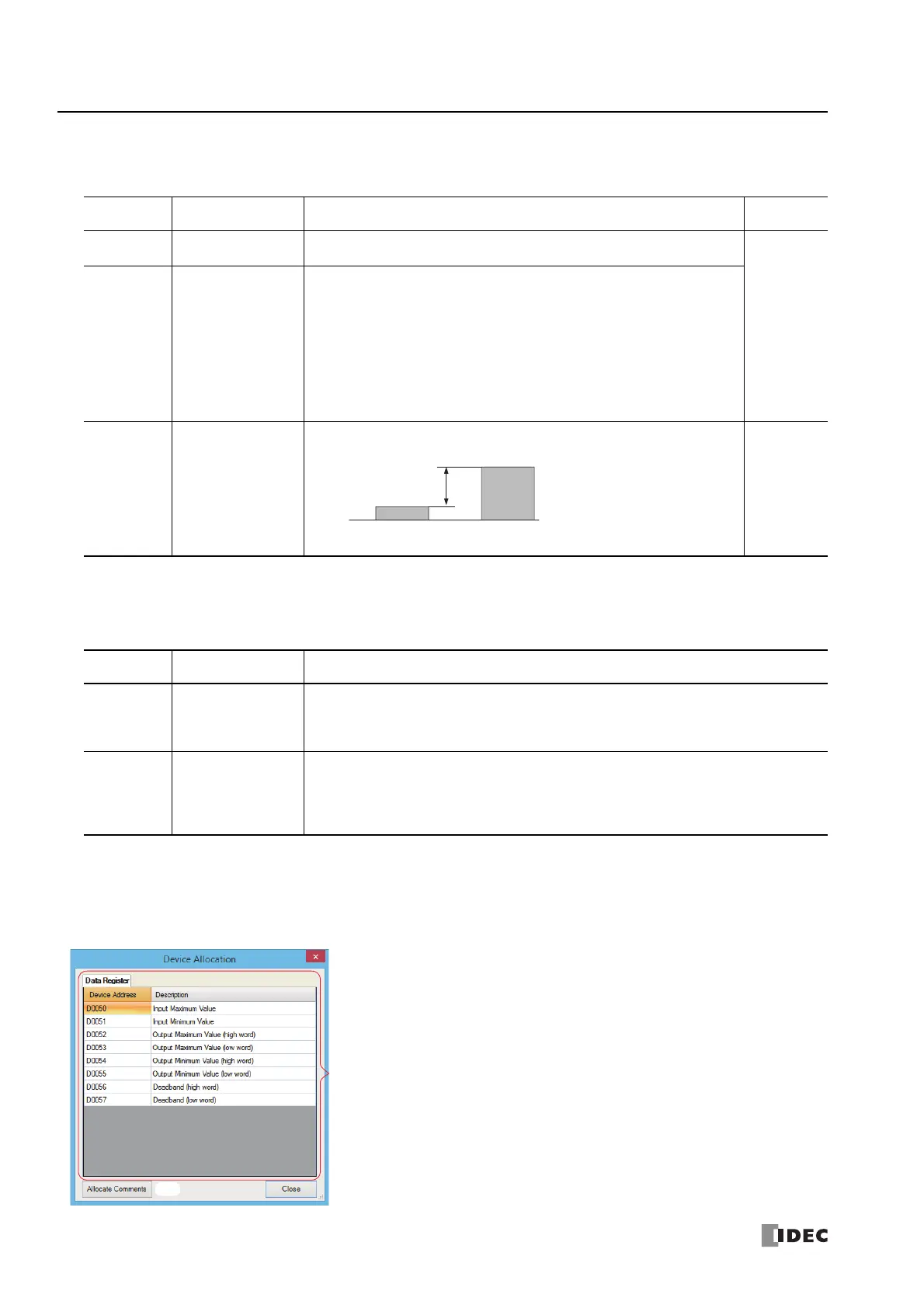
(6) Device Allocation
Click this button to display the Device Allocation dialog box. As shown next, a table of the data registers and internal
relays and their corresponding SCALE instruction settings are displayed in the dialog box (7). Click Allocate Comments (8)
and you can configure the comments for the data registers and internal relays that correspond to the content of the settings.
Device Allocation dialog box
Storage
Destination
Function Setting Data Types
D1+0
D1+1
Output value Stores the value after scaling with each scan.
F (float)
D1+2
D1+3
Output value
(dead band)
If the dead band is disabled (dead band (S2+6, S2+7) is 0), the output value
(D1+0, D1+1) is stored in the output value (dead band) with each scan.
If the dead band is enabled (dead band (S2+6, S2+7) is not 0), output value
(dead band) change notification (D2+0) turns on and the output value (D1+0,
D1+1) is stored in the output value (dead band) only when the absolute value of
the difference between the output value (D1+0, D1+1) and the output value
(dead band) is greater than or equal to the dead band (S2+6, S2+7)) (difference
≥ dead band (S2+6, S2+7)).
For details, see "Dead Band Function" on page 27-2.
D1+4
D1+5
Amount of output
change
Stores the absolute value of the difference between the output value (D1+0,
D1+1) and the output value (dead band) (D1+2, D1+3).
F (float)
*1
*1 The data range is 0 and 1.175494E-38 to 3.402823E+38.
Storage
Destination
Function Setting
D2+0
Output value
(dead band) change
notification
This relay turns on for one scan if the absolute value of the difference between the output value
(D1+0, D1+1) and the output value (dead band) (D1+2, D1+3) is greater than the dead band
(S2+6, S2+7). At that time, the output value (D1+0, D1+1) is stored in the output value (dead
band) (D1+2, D1+3).
D2+1
Input value warning
output
This relay turns on when the input value (S1) is greater than the input maximum value (S2+0) or
when the input value is less than the input minimum value (S2+1). At that time, if the input value
(S1) is greater than the input maximum value (S2+0), it is scaled by the input maximum value
(S2+0). If the input value (S1) is less than the input minimum value (S2+1), it is scaled by the input
minimum value (S2+1).
Absolute value of difference
(D1+4, D1+5)
Output value
(D1+0, D1+1)
Output value (dead band)
(D1+2, D1+3)

 Loading...