FC6A S
ERIES
MICROS
MART
L
ADDER
P
ROGRAMMING
M
ANUAL
FC9Y-B1726 27-7
27: F
LOW
C
ALCULATION
I
NSTRUCTIONS
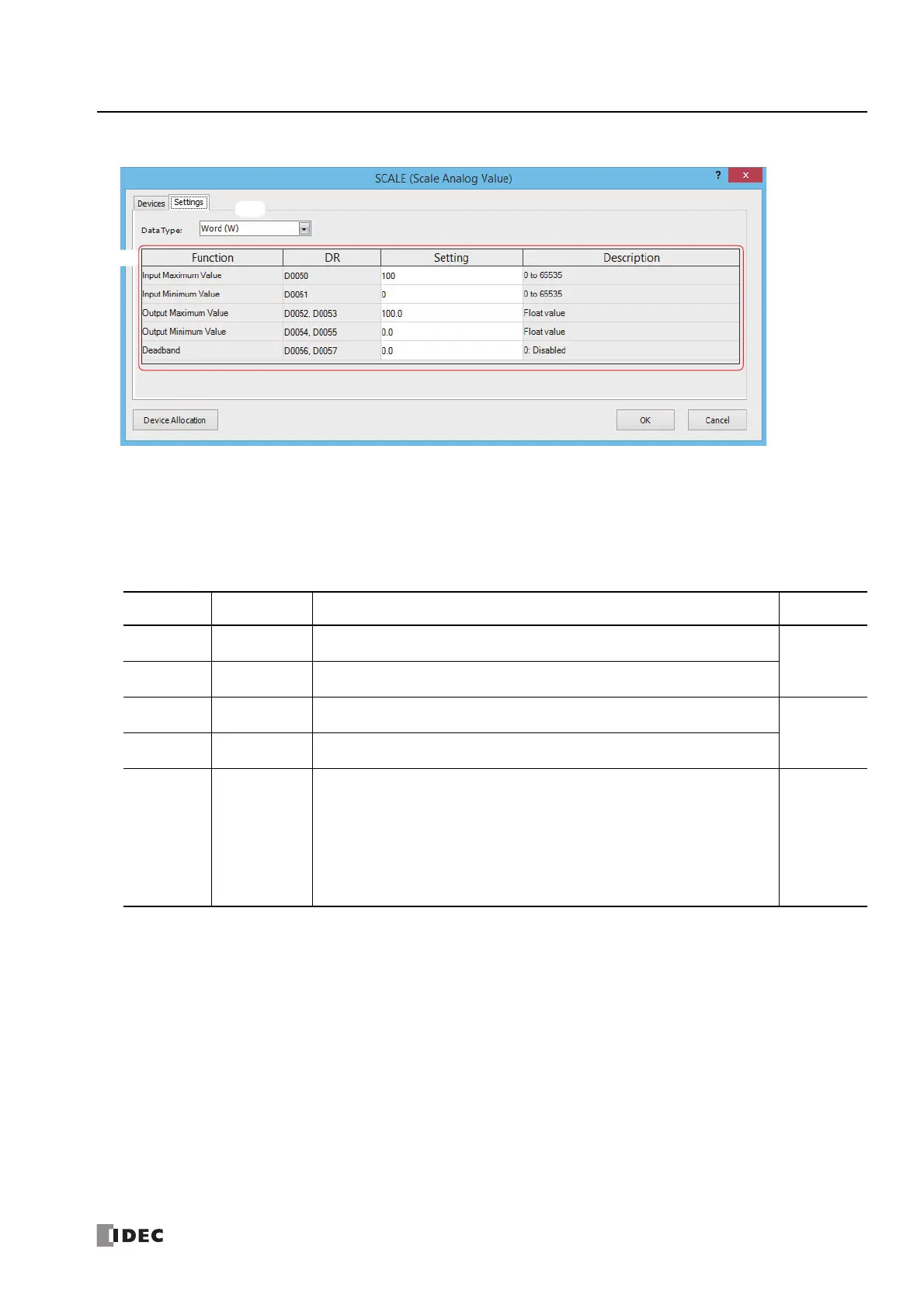
■ Settings tab
(1) Data Type
Select the data type of the input value (S1) as "W (word)" or "I (integer)".
(2) Initial Value
Configure the initial values of the functions that will be stored in the control registers when the initialization input is on. For
the range of initial values, see "S2: Control registers" on page 27-7.
S2: Control registers
Storage
Destination
Function Setting Data Types
S2+0
Input maximum
value
Set as input maximum value > input minimum value (S2+0)
*1
.
The initial value is 100.
W (word)
I (integer)
S2+1
Input minimum
value
Set as input minimum value < input maximum value (S2+1)
*1
.
The initial value is 0.
S2+2
S2+3
Output
maximum value
Set as output maximum value > output minimum value (S2+4, S2+5)
*1
.
The initial value is 100.0.
F (float)
S2+4
S2+5
Output
minimum value
Set as output minimum value < output maximum value (S2+2, S2+3)
*1
.
The initial value is 0.0.
S2+6
S2+7
Dead band
The absolute value of the difference between the output value (D1+0, D1+1) and the
output value (dead band (D1+2, D1+3) is sampled, and output value (dead band)
change notification (D2+0) turns on only if the absolute value of the difference is
greater than or equal to the dead band (difference ≥ dead band). At that time, the
output value (dead band) (D1+2, D1+3) is stored in the output value (D1+0, D1+1).
If the dead band is 0, the dead band function is disabled and the output value (D1+0,
D1+1) is stored in the output value (dead band) (D1+2, D1+3) with each scan.
The initial value is 0.
F (float)
*2
*1 If the conditions for the settings cannot be satisfied, a user program execution error will occur and the output value and output value (dead
band) will not be updated.
*2 The data range is 0 and 1.175494E-38 to 3.402823E+38.

 Loading...