27: F
LOW
C
ALCULATION
I
NSTRUCTIONS
27-14 FC6A S
ERIES
MICROS
MART
L
ADDER
P
ROGRAMMING
M
ANUAL
FC9Y-B1726
Settings
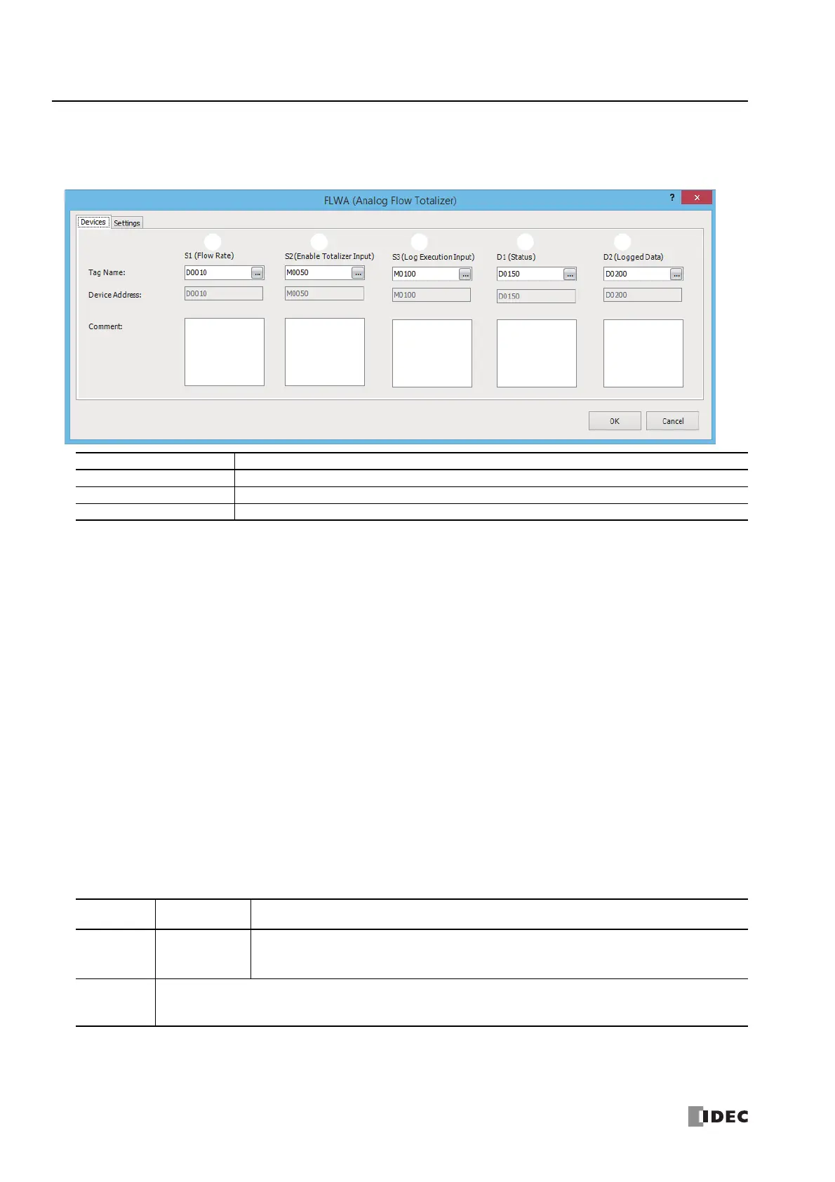
The FLWA (Analog Flow Totalizer) dialog box contains the Devices tab and the Settings tab.
■ Devices tab
(1) S1 (Source 1): Flow Rate
Specify the device that stores the flow rate. 2 continuous words (S1+0, S1+1) are used starting from the set device.
The valid range for flow rate is 0 or 1.175494E-38 to 3.402823E+38
*1
.
Note: If the flow rate value is outside the valid range, a user program execution error occurs, M8004 turns on, error code 28 is stored in D8006, and
execution of the instruction is canceled. 10 is also stored in the status (D1) at the same time.
For user program execution errors, see "User Program Execution Errors" on page 3-10.
(2) S2 (Source 2): Enable Totalizer Input
Specify the device to enable totalization processing of the flow rate.
When the enable totalizer input is off, totalization is paused. When on, totalization is executed.
For details on the enable totalizer input, see "Function Descriptions" on page 27-11.
(3) S3 (Source 3): Log Execution Input
Specify the device to execute and stop the logging process that updates the log and initializes the accumulated flow volume
work area and the accumulated time work area to "0".
When the log execution input changes from off to on, the logging process is executed.
For details on the log execution input, see "Log Output Function" on page 27-13.
(4) D1 (Destination 1): Status
Specify the device to store the status including the error during FLWA instruction execution. 10 continuous words are used
starting from the set device.
Settings Description
Tag name Specifies the tag name or the device address for the device.
Device address Shows the device address that corresponds to the tag name.
Comment Shows the comment for the device address. This item can be edited.
*1 The upper and lower data registers change according to the 32-bit data storage method specified. For details, see Chapter 3
"Instructions Reference" - "32-bit Data Storage" on page 3-9.
Storage
Destination
Function Description
D1+0 Operation status
Stores the status including the error during FLWA instruction execution.
0
10
: Normal
: Flow rate out of range during sampling
D1+1
D1+9
System work area

 Loading...