SETUP
4-16 46882/439
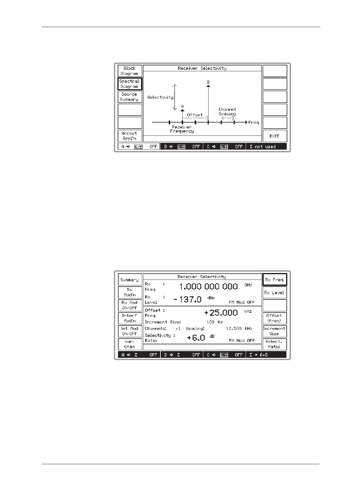
(3) Press [Spectral Diagram] which displays the Receiver Selectivity spectral diagram as shown
in Fig. 4-21 below.
B3405
Fig. 4-21 Receiver selectivity spectral diagram
(4) As shown by the spectral diagram, the A source is set to the receiver channel and the B
source is offset higher in frequency than the A source at a multiple of the channel spacing.
You can reverse this setting so that the B source is at the lower frequency by entering a
negative offset. The B source is set higher in level than the A source.
(5) If you wish to continue, press [Accept Appl’n], otherwise press [EXIT] which returns you to
the Applications Selection Menu to enable you to select an alternative test.
(6) Pressing [Accept Appl’n] displays a screen similar to that shown in Fig. 4-22 below. The
screen is split horizontally into two, with the upper part displaying the receiver parameters
and the lower part displaying the interferer parameters. Note that in the signal source field at
the bottom of the screen, the A and B sources are shown connected to the combiner by
∑
= A+B.
B3406
Fig. 4-22 Receiver selectivity: application accepted
(7) Select [Rx Freq] and [Rx Level] if you want to change these parameters for the A source, but
note that the RF level limit is +4 dBm when the selectivity ratio is set to 0 or to a negative
value.
(8) If you want to apply modulation to the A source press the [Rx Mod’n] key to access the
Receiver Modulation Setup Menu shown in Fig. 4-23 below. At the conclusion press [EXIT]
to return to the previous screen.

 Loading...