SETUP
4-2 46882/439
Summary
The setup menus are used to route the outputs from the signal sources to either their individual RF
OUTPUT sockets or, via the combiner, to the COMBINER RF OUTPUT socket and additionally
allow the sources to be coupled together by a mathematical formula in both frequency and level.
The routing is set using the combiner setup facility and the coupling parameters are enabled and
set using the coupling setup facility.
The applications facility allows the user to select one of a number of common test configurations,
such as intermodulation testing, for two or three signal sources. When an application is selected
the most appropriate signal routing is automatically chosen and the required coupling controls
enabled. Control parameters are then redefined in terms of the measurement being performed to
minimize the number of parameter entries required. For example for intermodulation testing with
equal amplitude sources, only one RF level control is provided and this automatically sets the level
of all of the sources. Control parameters are described in terms which are relevant to the
measurement being performed.
Setup menu selection
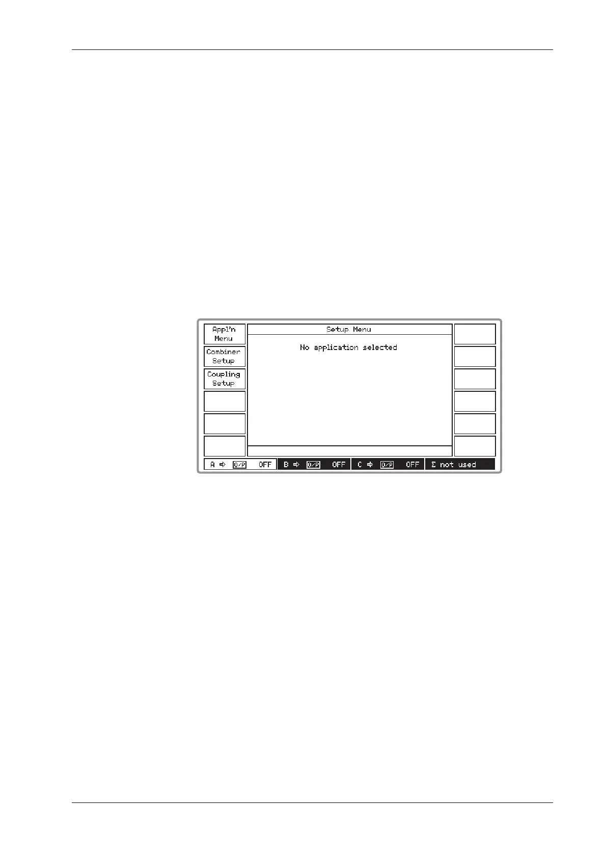
Pressing the [SETUP] key gains access to the Setup Menu similar to that shown in Fig. 4-1 below.
B3411
Fig. 4-1 Setup menu (shown for three sources fitted)
The [Appl’n Menu] key accesses the Applications Selection Menu which enables you to select one
of the three predefined applications. The [Combiner Setup] key accesses the Combiner Setup
Menu which enables you to connect the signal sources in any combination to the combiner. The
combined signal is then available at the COMBINED RF OUTPUT socket. [Coupling Setup]
accesses the Frequency and Level Coupling menu which enables you to couple the B and C
sources to the A source. These sources can then track the A source by means of a level offset and
a frequency and harmonic offset.