LOCAL OPERATION
3-22 46882/439
(7) Press [Phase Diff] and adjust the phase using the control knob. Turn clockwise to advance
the phase and anticlockwise to retard the phase. Note that if you have set the source phase
and subsequently adjusted the source frequency or changed the waveform, the menu Phase
Difference: value will be blanked. This is because the value will then be indeterminate due
to the adjustment or changed waveform.
(8) To establish a reference, the displayed phase shift can be reset to 0.0° by pressing [Reset
Phase].
(9) Press [EXIT] to return to the Sig Gen menu.
External source coupling
Having selected an external modulation mode, you can select the type of external coupling as
follows:
(1) Press [SIG GEN] and show the Sig Gen menu for a single modulation mode.
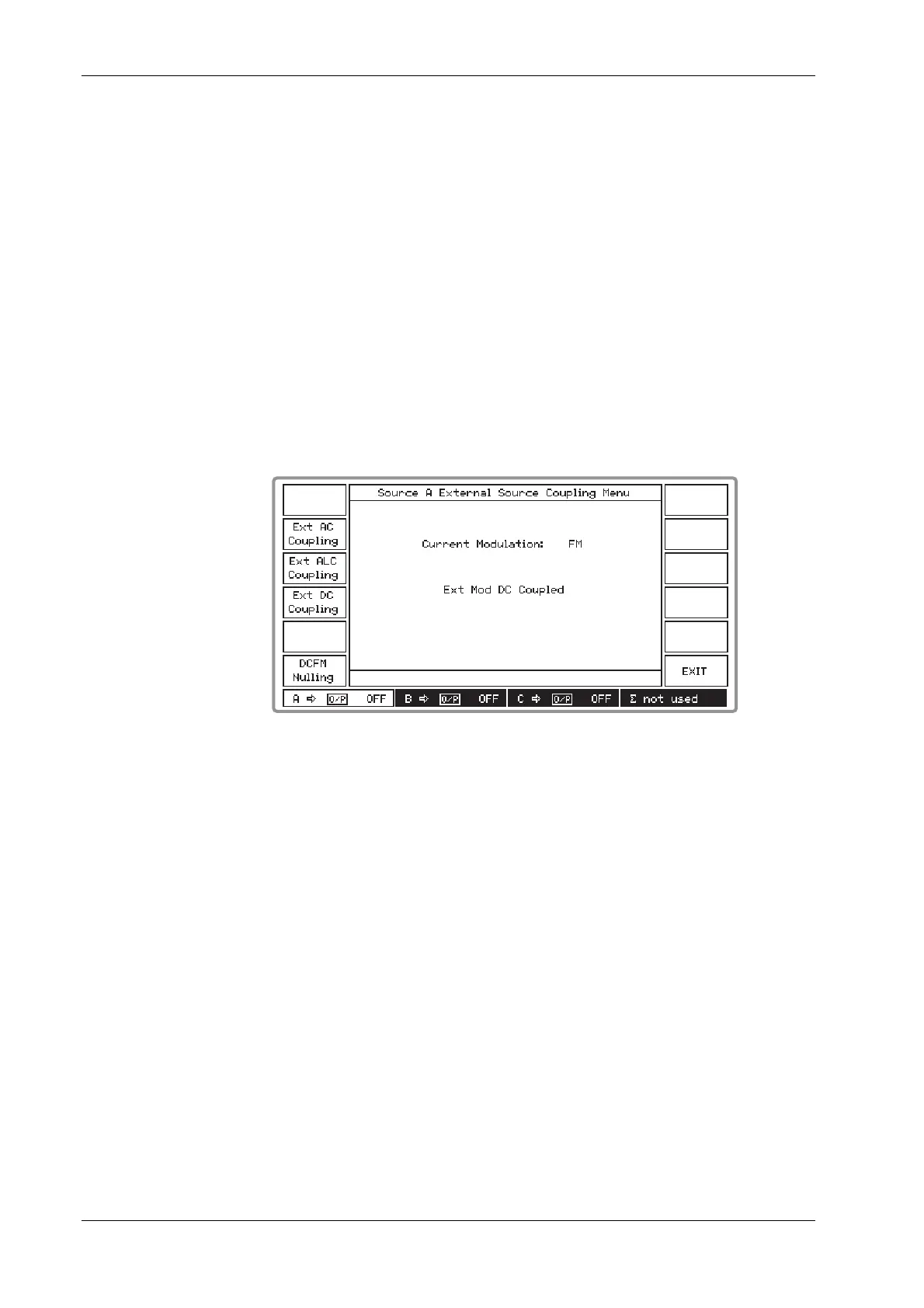
(2) Press [Select Coupling] to display the External Source Coupling Menu. This shows the
currently selected modulation and external coupling (see Fig. 3-15 below). The [DCFM
Nulling] key appears only during FM external modulation mode with DC coupling.
B3417
Fig. 3-15 External source coupling menu
(3) Select between [Ext AC Coupling], [Ext ALC Coupling] and [Ext DC Coupling]. The screen
changes to show your new coupling selection.
(4) Apply a signal to the MOD I/O socket.
(5) When Automatic Levelling Control is selected by pressing [Ext ALC Coupling], and the
error message Err 511: ALC too high or Err:512: ALC too low is displayed, the level must be
adjusted. Adjust the signal level until it is within the 0.75 to 1.25 V RMS ALC range of the
source.
(6) Press [EXIT] to return to the Sig Gen menu.
DCFM nulling
For a DC-coupled external signal, small frequency offsets can be reduced by using the DCFM
nulling facility. Operation is as follows:
(1) With FM External mode previously selected from the Modulation Mode Selection Menu
press the [Ext DC Coupling] key shown in Fig. 3-15 above.
(2) Connect your ground reference to the MOD I/O socket.
(3) Press the [DCFM Nulling] key which is now displayed. * DCFM Nulling * appears during
the nulling process and when it disappears the process is completed.