ACCEPTANCE TESTING
7-26 46882/439
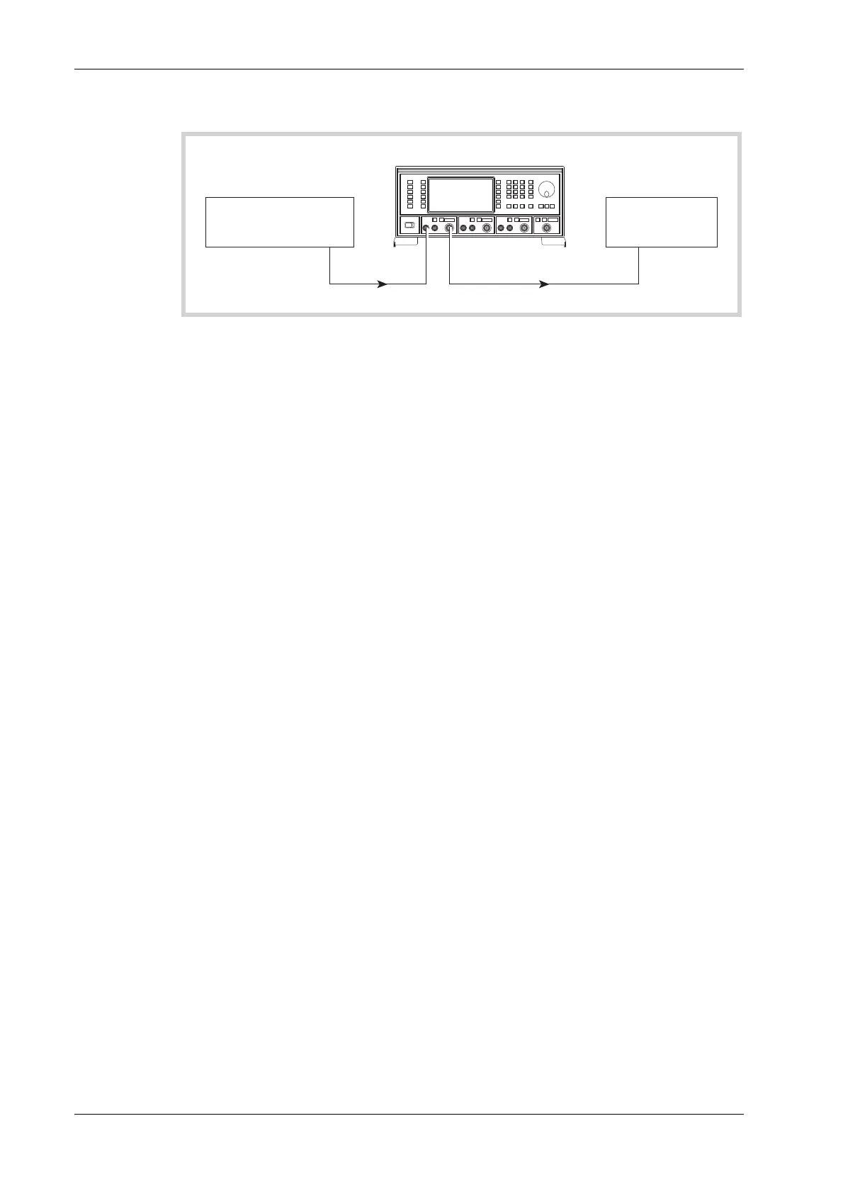
Pulse modulation rise and fall time
UUT
PULSE
INPUT
RF
OUTPUT
OUTPUT
C3494
Function
Generator
Oscilloscope
Fig. 7-14 Pulse modulation rise and fall time test set-up
Test procedure
(1) Connect the test equipment as shown in Fig. 7-14.
(2) On the UUT set source A to:
[Carrier Freq] 50 [MHz]
[RF Level] +7 [dB]
[UTIL]
[Mod’n Mode] [Pulse Enab/Dis] [EXIT] [SIG GEN]
[Pulse ON/OFF]
(3) Set the function generator to produce 10 kHz, 0 V to +5 V square wave.
(4) Adjust the oscilloscope controls such that the rise time of the envelope can be measured.
(5) Measure the rise time between the 10% to 90% points, checking that it is within the
specification shown in Table 7-48.
(6)
Repeat (4) to (5) for the fall time of the envelope.
Modulation oscillator
Specification
Frequency range:
0.01 Hz to 20 kHz.
Resolution:
0.01 Hz
Frequency accuracy
As frequency standard.
Distortion:
Less than 0.1% at 1 kHz.
Waveforms:
Sine (to 20 kHz), triangle or square wave (to 3 kHz).
Square wave jitter <6.4 μs on any edge.
Output:
2 V RMS EMF from a 600 Ω source impedance.