46882/439 4-3
Combiner setup
This facility allows the user to route an individual signal source (A, B or C) to either its designated
separate RF OUTPUT connector or through the combiner to the COMBINED RF OUTPUT
connector. The current routing of the signal sources is always indicated by the source field at the
bottom of the display. If the sources are all routed to their separate connectors the combiner panel
shows
∑
not used.
Combiner selection
Select the required signal source − combiner configuration as follows:
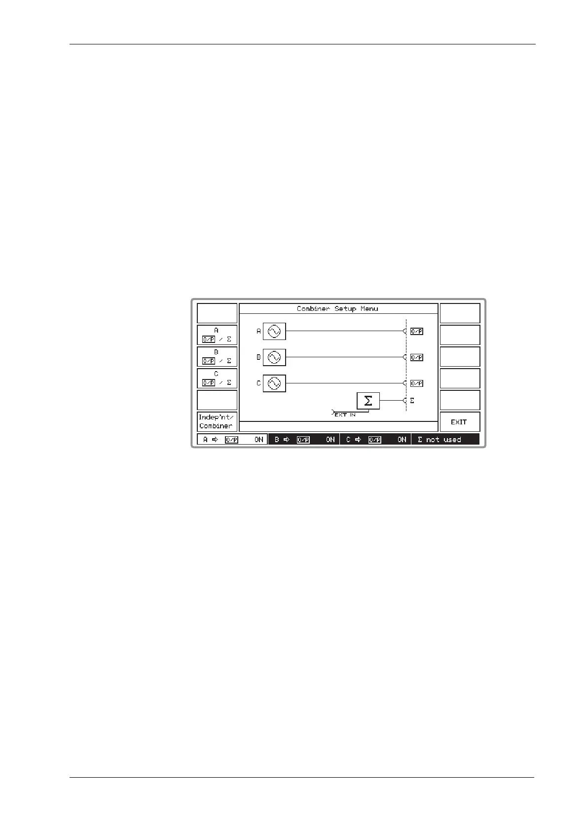
(1) On the Setup Menu press [Combiner Setup] to display the Combiner Setup Menu. This
shows a graphical display of the current combiner setup similar to Fig. 4-2 below.
B3412
Fig. 4-2 Combiner setup menu
(2) Pressing the [O/P /
∑]
key for a particular source toggles between connecting the source to
its own RF OUTPUT connector (shown by O/P on the display) or, via the combiner, to the
COMBINED RF OUTPUT connector (shown by
∑
). Use these keys to select your required
configuration. As shown by the display, the EXT I/P socket is permanently connected to the
combiner. But note that switching the C source to the combiner requires you to configure a
rear-panel link (see ‘External source’ below).
(3) At each change in configuration the A, B and C source panels and the combined output
∑
panel at the bottom of the display change to show the new destinations. These settings are
repeated on all menus.
(4) Pressing the [Indep’nt/Combiner] key switches between the current configuration having a
combiner output and all sources having independent outputs. This provides a convenient
way to restore the sources to normal, independent operation.
(5) Selecting [EXIT] returns you to the Setup Menu.