TEST PROCEDURES
46882/439 7-17
FM deviation and distortion
Test procedure
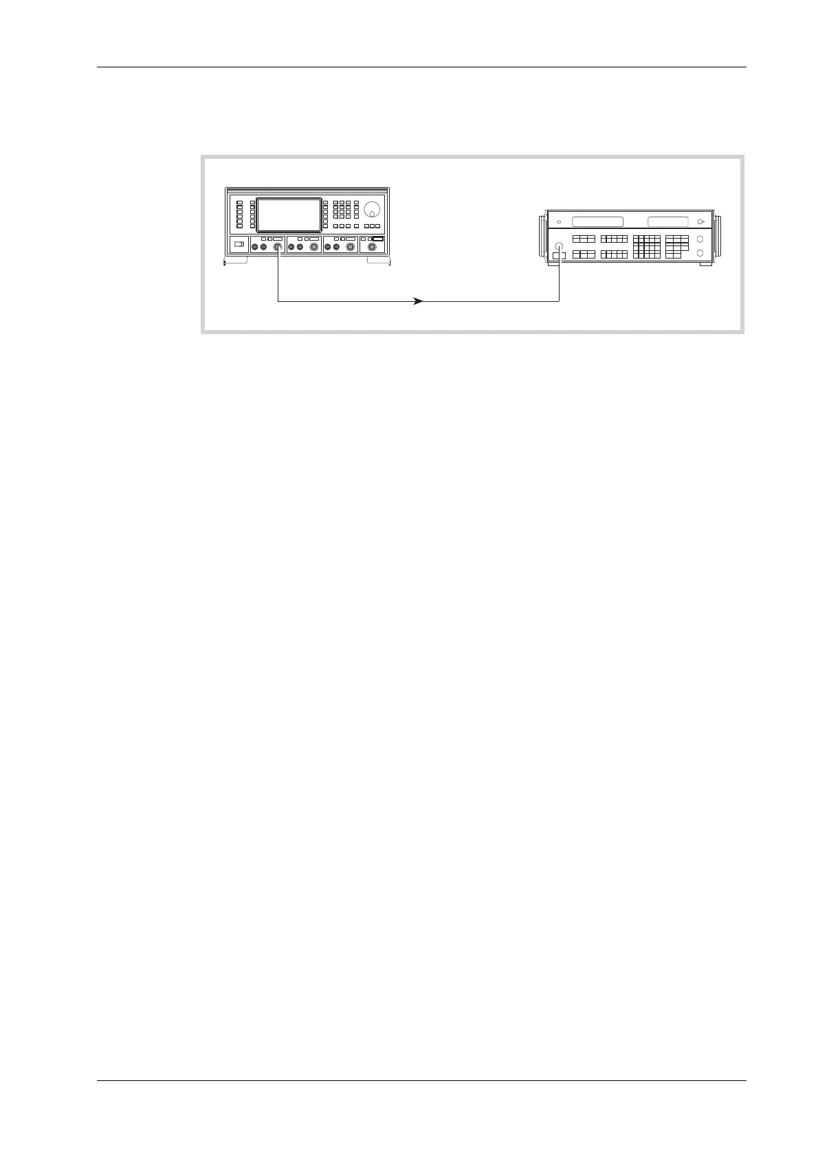
2305
Modulation Meter
UUT
RF
OUTPUT
RF
INPUT
C3488
Fig. 7-9 Internal modulation and modulation distortion test set-up
(1) Connect the test equipment as shown in Fig. 7-9.
(2) On the UUT set source A to:
[Carrier Freq] 10 [MHz]
[RF Level] 0 [dB]
[FM Devn] 100 [kHz]
[FM ON/OFF]
(3) On the modulation meter, select CAL, FM, 50 Hz ⇒ 15 kHz filter.
(4) Measure the FM accuracy and distortion at the carrier frequencies shown in Table 7-30,
checking that the results are within specification.
(5
) Repeat (2) to (4) for source B and, if Option 1 is fitted, source C.
FM scale shape
Test procedure
(1) Connect the test equipment as shown in Fig. 7-9.
(2) On the UUT set source A to:
[Carrier Freq] 15 [MHz]
[RF Level] 0 [dB]
[FM Devn] 100 [kHz]
[FM ON/OFF]
(3) On the modulation meter, select CAL, FM, 50 Hz ⇒ 15 kHz filter.
(4) Measure the FM accuracy at the deviations shown in Table 7-31, checking that the results
are within specification.
(5
) Repeat (2) to (4) for source B and, if Option 1 is fitted, source C.
Carrier error
Test procedure
(1) Connect the test equipment as shown in Fig. 7-9.
(2) On the UUT set source A to:
[Carrier Freq] 1200 [MHz]
[RF Level] 0 [dB]
(3) On the modulation meter select CARRIER ERROR. The FREQUENCY display will read
0.00 kHz.
UUT