TEST PROCEDURES
46882/439 7-25
(3) On the UUT set source A to:
[Carrier Freq] 32 [MHz]
[RF Level] −7 [dB]
[UTIL]
[Mod’n Mode] [Pulse Enab/Dis] [EXIT] [SIG GEN]
[Pulse ON/OFF]
(4) Set the function generator to provide +5 V DC. The RF output will now be enabled.
(5) Record the output level measured by the power meter against each of the carrier frequencies
shown in Table 7-45, checking that the resu
lts are within specification.
(6) Set the UUT RF level to +4 dBm and repeat (5) using Table 7-46.
(7
) Repeat (3) to (6) for source B and, if Option 1 is fitted, source C.
Pulse modulation on/off ratio
2386/238 0
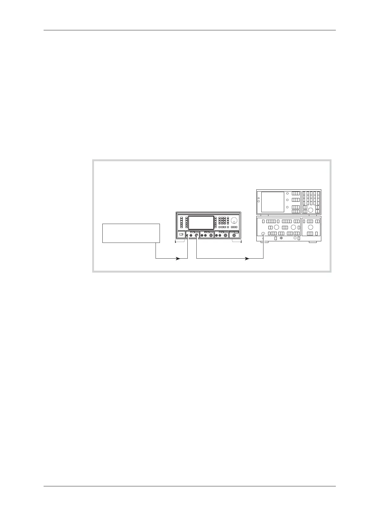
Spectrum Analyser
and Display
PULSE
INPUT
RF
OUTPUT
RF
INPUT
OUTPUT
C3495
Function
Generator
UUT
Fig. 7-13 Pulse modulation on/off ratio test set-up
Test procedure
(1) Press CAL on the spectrum analyzer.
(2) Connect the test equipment as shown in Fig. 7-13.
(3) On the UUT set source A to:
[Carrier Freq] 32 [MHz]
[RF Level] 0 [dB]
[UTIL]
[Mod’n Mode] [Pulse Enab/Dis] [EXIT] [SIG GEN]
[Pulse ON/OFF]
(4) Set the function generator to provide +5 V DC. The RF output will now be enabled.
(5) Tune the spectrum analyzer to the same frequency as the signal generator.
(6) Press PEAK FIND on the spectrum analyzer and note the output level.
(7) Apply a short circuit to the PULSE INPUT socket.
(8) Again note the output level measured by the spectrum analyzer.
(9) The difference between the levels recorded in (6) and (8) is the pulse mod on/off ratio.
Check that the ratio is within specification using Table 7-47.
(10)
Repeat (5) to (9) for each of the frequencies shown in Table 7-47.
(1
1) Repeat (3) to (10) for source B and, if Option 1 is fitted, source C.