SETUP
4-8 46882/439
Amplifier intermodulation distortion application
Intermodulation tests on amplifiers are a good indication of the linearity of an amplifier. Many
communication systems require devices able to carry two or more signals without introducing
spurious frequencies which might affect system performance. The 2026 can support 2-tone and (if
three sources are fitted) 3-tone intermodulation testing. The number of tones can also be increased
by using the external source input, EXT I/P, for the connection of external generators.
Two-tone test
In this test two tones are input to an amplifier. Amplifier output will comprise not only the two
applied tones but also, due to amplifier non-linearity, intermodulation products. One tone is
provided from source A at the required amplifier frequency. The second interfering tone is
provided from source B at a different frequency but same amplitude.
Three-tone test
In this test three tones are input to an amplifier. As described for the two-tone test above, the
amplifier’s non-linearity gives rise to distortion products. When these signals interfere with each
other they will either add together to produce a larger amplitude signal or cancel each other
depending on the phase of each signal.
The three tones used are: one at the centre frequency (from source A), and two additional,
interfering signals (from sources B and C). To find the worst possible case for the amplifier, the
phase of one of the signals must be adjusted until the distortion products rise to a maximum level.
In the 2026 the peak levels can be identified by phase (or frequency) modulating source C and
using a peak hold on the measuring instrument. Alternatively, the phase of source C can be
adjusted (with no modulation applied) until a peak response is found.
When phase or frequency modulation is used to peak the measurement rate a default modulation
rate of 10 Hz and deviation of 3.2 radians is provided. This can be adjusted by the user to suit the
measuring instrument being used.
Procedure
You can carry out an intermodulation distortion test on an amplifier as follows:
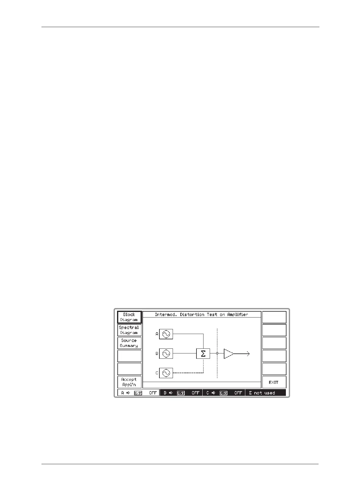
(1) Press [Amplifier IM] which displays the Intermod. Distortion Test on Amplifier block
diagram as shown in Fig. 4-6 below.
B3416
Fig. 4-6 Intermod. distortion test on amplifier block diagram
(2) Connect the amplifier under test to the COMBINED RF OUTPUT socket as shown by the
block diagram. Since for a 2-tone test the C source is not used, its connection to the
combiner is shown dotted.