TEST PROCEDURES
46882/439 7-27
Test equipment
Description Minimum specification Example
Frequency
counter
10 kHz to 2.4 GHz IFR 2440
50 Ω load
(termination)
1 W, 50 Ω nominal impedance, DC to 2.4 GHz
Lucas Weinschel
M1404N
Audio analyzer Capable of measuring THD of 0.01% at 1 kHz Rohde & Schwarz
UPA3
Modulation oscillator frequencies
Test procedure
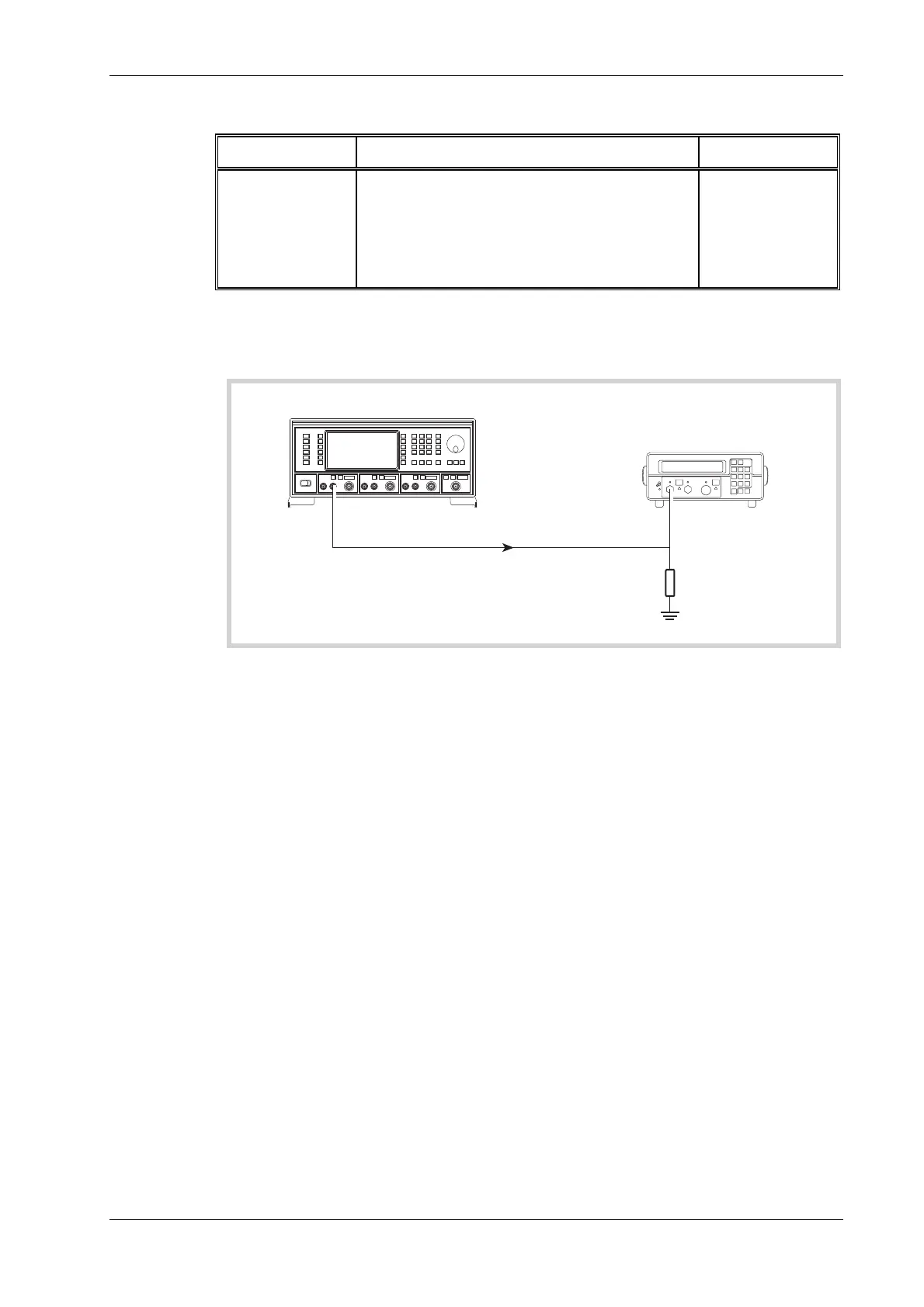
C3502
UUT
MOD I/O A
INPUT
2440
Frequency Counter
50
load
Ω
Fig. 7-15 Modulation oscillator frequency test set-up
(1) Connect the test equipment as shown in Fig. 7-15.
(2) On the UUT set source A to:
[MOD ON/OFF] (To enable modulation source)
[FM Mod Freq] 10 Hz
(3) Record the frequency measured by the counter against each of the modulation oscillator
frequencies shown in Table 7-49.
(4
) Repeat (2) to (3) for source B and, if Option 1 is fitted, source C.