TEST PROCEDURES
46882/439 7-9
(3) On the UUT set source A to:
[Carrier Freq] 1 [MHz]
[RF Level] −18 [dB]
[SET UP]
[Combiner Setup] [A O/P /
Σ
] [EXIT] [SIG GEN]
(4) Record the output level measured by the power meter against each of the carrier frequencies
shown in Table 7-14 checking that the results are with
in specification.
(5) Set the UUT RF level to −13 dBm and repeat (4) using Table 7-15.
(6)
Set the UUT RF level to +4 dBm and repeat (4) using Table 7-16.
(7
) Repeat (1) to (6) for source B and, if Option 1 is fitted, source C, ensuring that only one
source at a time is routed to the combiner.
Carrier frequency accuracy
This check provides a conventional method of checking the signal generator frequency locking
circuitry. It will confirm correct operation of phase locked loops and dividers. Overall accuracy is
determined by the instrument’s internal reference standard.
Specification
Frequency range:
10 kHz to 2.4 GHz.
Accuracy:
Determined by the frequency standard accuracy.
Resolution:
1 Hz
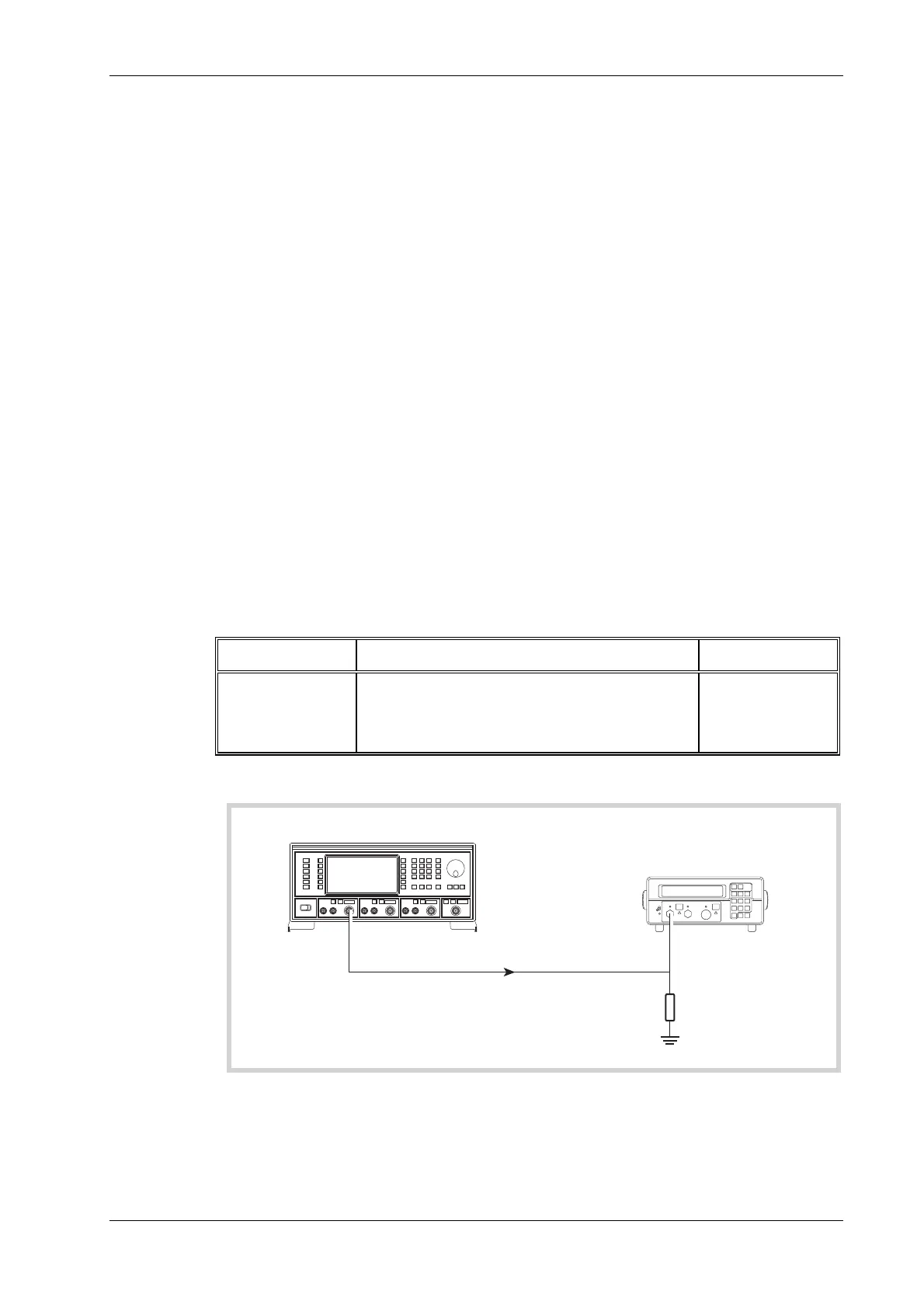
Test equipment
Description Minimum specification Example
Frequency
counter
10 kHz to 2.4 GHz EIP 535B or
IFR 2440
50 Ω load
(termination)
1 W, 50 Ω nominal impedance, DC to 2.4 GHz
Lucas Weinschel
M1404N
Test procedure
C3503
UUT
RF OUTPUT A
INPUT
2440
Frequency Counter
50
load
Ω
Fig. 7-3 Carrier frequency accuracy test set-up
(1) Connect the test equipment as shown in Fig. 7-3.

 Loading...