INDIVIDUAL SOURCE OPERATION
46882/439 3-25
(5) Press [Pulse ON/OFF] to toggle between the ON and OFF states until the display shows
Pulse ON.
When ON the carrier is controlled by the logic level applied to the PULSE INPUT socket. A
logical ‘1’ (a voltage between 3.5 and 5 V) allows carrier output, a logical ‘0’ (a voltage
between 0 and 1.0 V) suppresses it. Turning pulse mod OFF effectively applies a logical ‘1’
allowing carrier output.
FSK selection
The instrument accepts logic level inputs to the AUXILIARY PORT connector to produce an FSK
modulated output signal from each source. The input data is sampled at 100 kHz and produces a
2- or 4-level shift waveform which is filtered by a 20 kHz Bessel filter and applied to the carrier.
Frequency shift keying is selected as follows:
(1) Press [UTIL] to display the Utilities Selection Menu 1. If the Utilities Selection Menu 2 is
displayed, it will be necessary to press the [Utils Menu 1] key.
(2) Select [Mod’n Mode] to display the Modulation Mode Selection Menu.
(3) Use the [Up] and [Down] keys to move the selection box over the required 2FSK or 4FSK
modulation mode.
(4) Press [Select Mode]. The display changes to show your new current modulation mode.
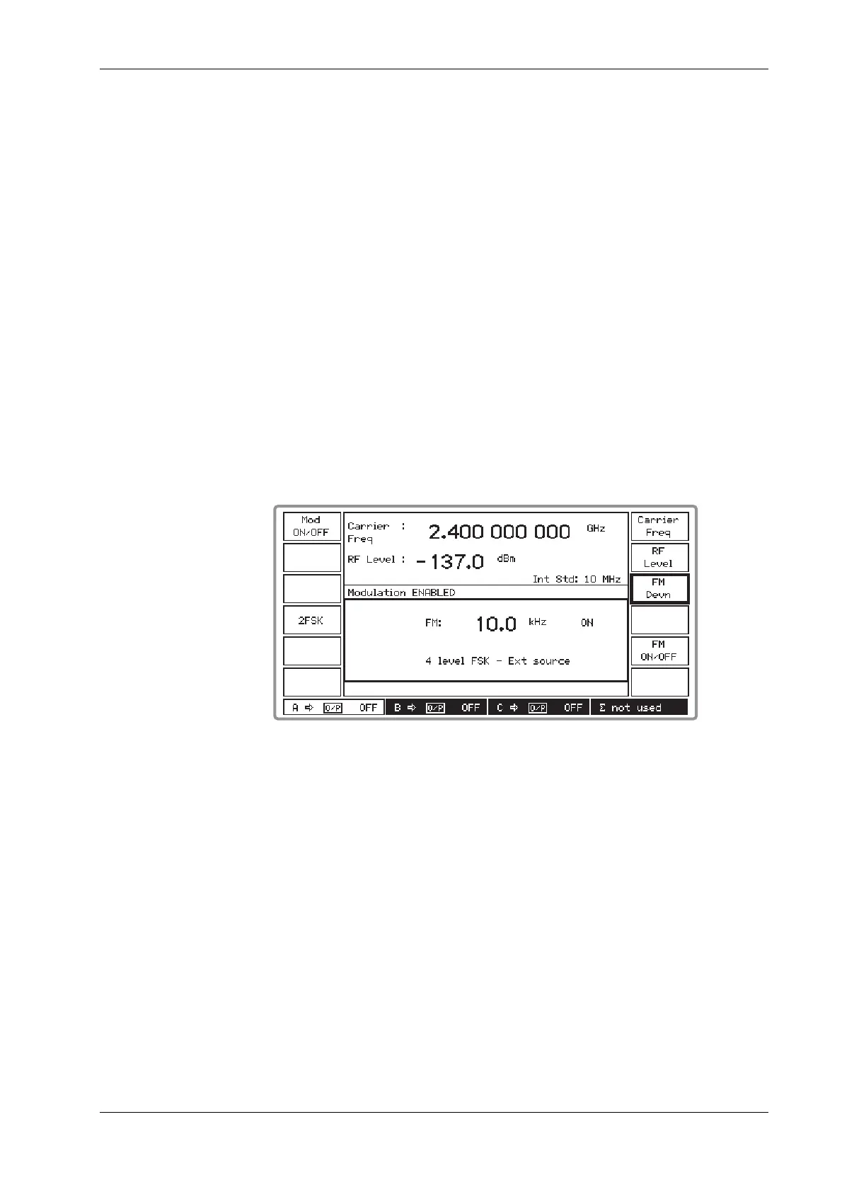
(5) Press [SIG GEN] to display the Sig Gen menu. This has been modified to show either 2 level
FSK − Ext source or 4 level FSK
−
Ext source in the modulation field (see Fig. 3-17 below).
B3474
Fig. 3-17 Sig Gen menu with 4FSK selected
(6) Press [FM Devn], enter the required deviation and terminate with the [Hz] or [kHz] key. If
you exceed the 100 kHz deviation limit the entered value is automatically reset to the
maximum allowed value.
(7) If FSK is turned off (either locally with [FM ON/OFF] or globally with [Mod ON/OFF]) no
frequency shift is applied to the carrier.
For information on the use of the AUXILIARY PORT connector for FSK operation see Chapter 2
‘Auxiliary port connector’ and ‘FSK operation’.

 Loading...