ACCEPTANCE TESTING
7-14 46882/439
(7) If using the 2386 Spectrum Analyzer select:
VOLTS/DIV
REF LEVEL 0.1 μV
2nd FUNCT RF ATTEN ⇓ (to set 0 dB input attenuation)
(8) Hold the 2-turn loop not less than 25 mm from the UUT at various points around its case
ensuring that the worst case leakage indicated on the spectrum analyzer does not exceed
that shown in Table 7-25.
(9)
Repeat (3) to (8) for each of the carrier frequencies shown in Table 7-25.
(1
0) Repeat (3) to (9) for source B and, if Option 1 is fitted, source C.
Combined RF output
Specification
Harmonics:
Typically better than −30 dBc for RF levels up to −14 dBm.
Typically better than −25 dBc for RF levels up to +4 dBm (0 dBm
above 1.2 GHz). Unspecified below 1 MHz.
Isolation:
Better than 80 dB between individual outputs in use.
Better than 60 dB from a used individual output to the combiner output.
Better than 40 dB between the combiner output and an unused
individual output.
2-tone intermodulation:
At an RF level output of 0 dBm on the combiner into a load VSWR of
2:1 or better:
From 10 MHz to 2.4 GHz, < −80 dBc.
From 5 MHz to 10 MHz, < −75 dBc.
Useable but unspecified down to 1 MHz.
Test equipment
Description Minimum specification Example
50 Ω load 1 W, 50 Ω nominal impedance, DC to 2.4 GHz
Lucas Weinschel
M1404N
T-piece Precision N-type
Spectrum
analyzer
DC to 2.4 GHz frequency coverage Anritsu MS2602A
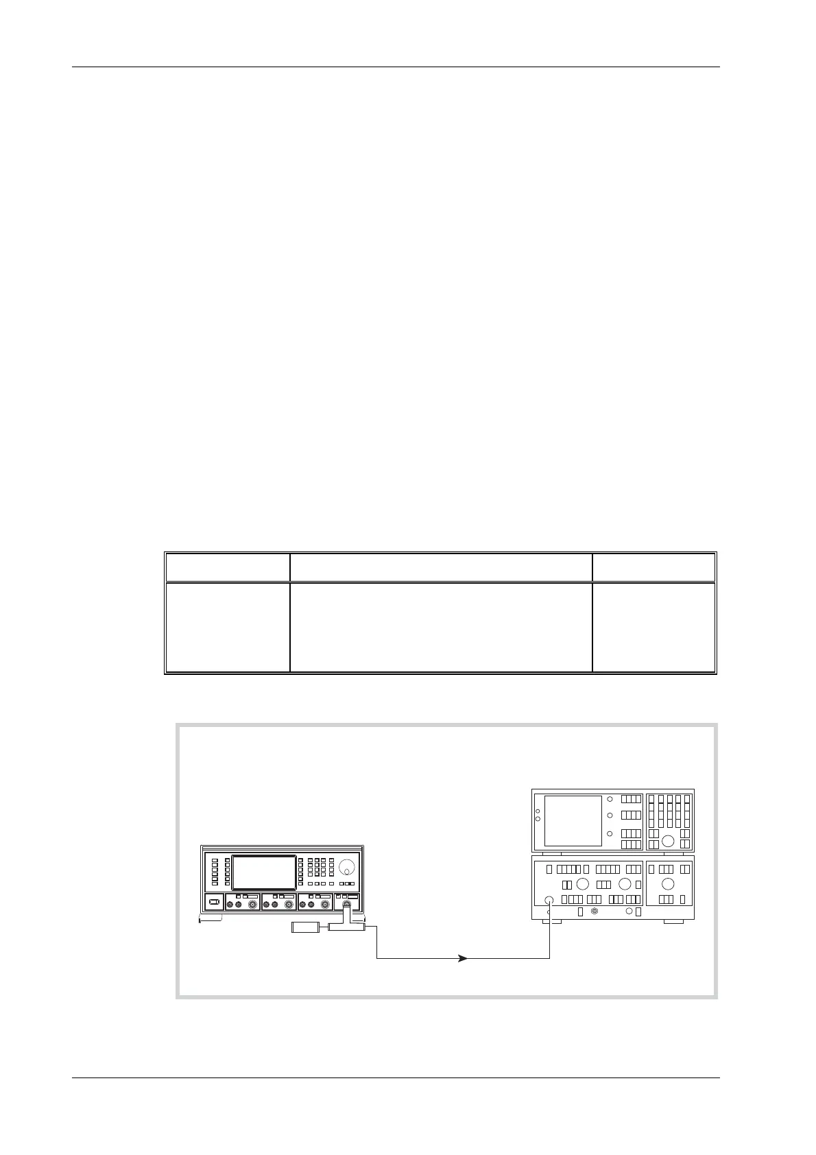
Intermodulation
UUT
2386/2380
Spectrum Analyzer
and Display
C4697
RF
INPUT
RF
OUTPUT
50
load
W
Fig. 7-8 Combined output intermodulation test set-up

 Loading...