SETUP
4-12 46882/439
Receiver two-tone intermodulation application
When a receiver is demodulating a low level input signal, it is possible for two-high level
out-of-band signals to generate intermodulation products in the receiver which interfere with the
wanted signal. Receivers have to be tested for their susceptibility to such signals to ensure that the
communication system is robust in adverse conditions.
To perform a receiver intermodulation test an in-channel wanted signal is applied to the receiver
and two high-level signals are added to it so that their intermodulation products are at the receiver
input frequency. Typically one of these high-level signals is modulated. This application allows
both in-channel and interfering signals to be modulated.
Procedure
You can carry out a two-tone intermodulation test on a receiver as follows:
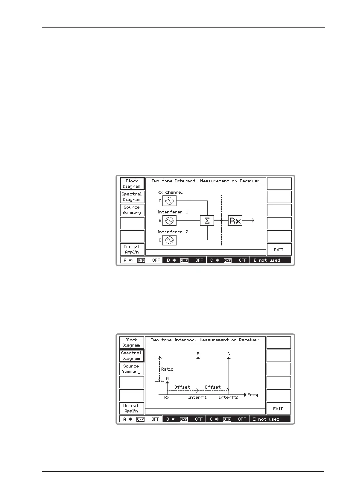
(1) Press [Receiver 2tone IM] which displays the Two-tone Intermod. Measurement on Receiver
block diagram as shown in Fig. 4-13 below.
B3397
Fig. 4-13 Two-tone intermod. measurement on receiver block diagram
(2) Connect the receiver under test to the COMBINED RF OUTPUT socket as shown by the
block diagram.
(3) Press [Spectral Diagram] which displays the Two-tone Intermod. Measurement on Receiver
spectral diagram as shown in Fig. 4-14 below.
B3398
Fig. 4-14 Two-tone intermod. measurement on receiver: spectral diagram

 Loading...