SETUP
4-4 46882/439
External source
Provision is made on the rear panel for connecting an external signal generator to the combiner via
the EXT I/P connector.
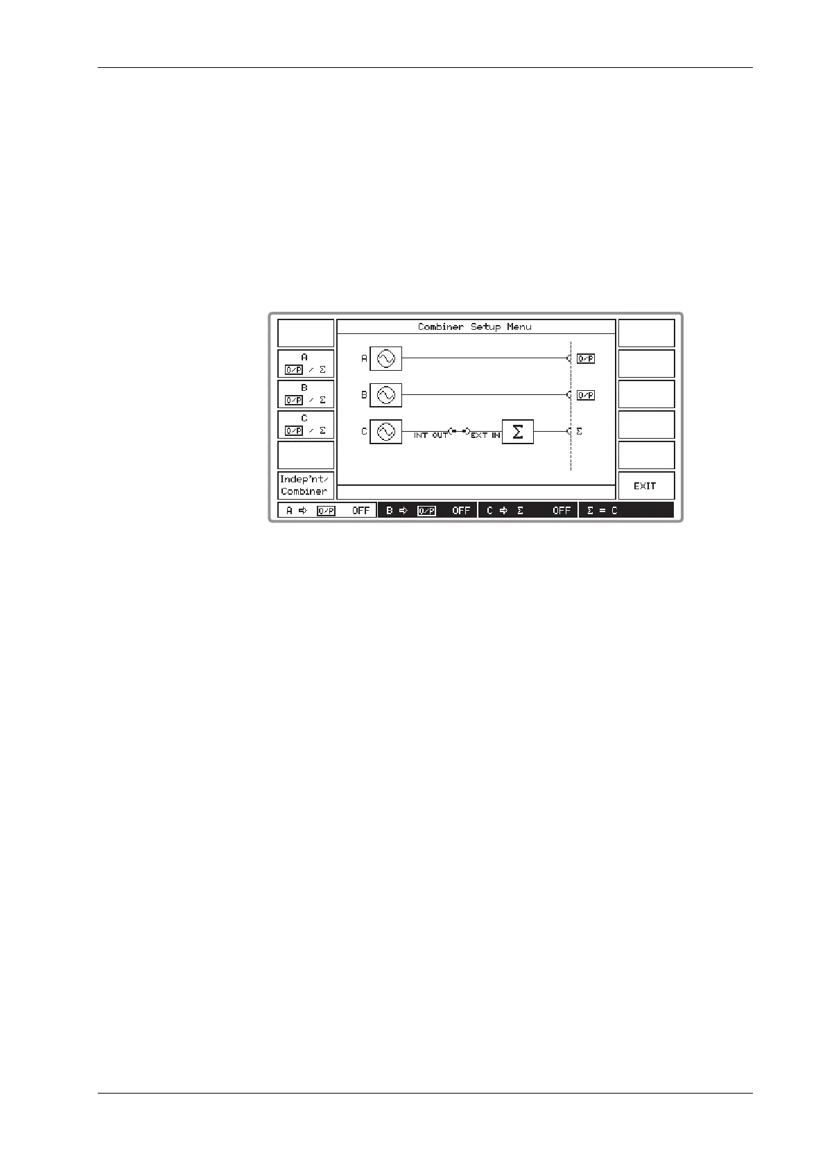
For a generator fitted with three internal sources an additional connector, INT O/P, is fitted. The
EXT I/P and INT O/P sockets effectively interrupt the C output to the combiner. To route the C
source output to the combiner the two connectors are linked by the supplied coaxial jumper lead as
shown in Fig. 4-3 below. To use an external source, remove the coaxial jumper lead using an
SMA torque spanner and connect the external signal to the EXT I/P connector as shown in
Fig. 4-2 above. When unused, always terminate the INT O/P connector by the attached 50 Ω load
to prevent signal radiation from the C source.
B3413
Fig. 4-3 Combiner setup menu, showing link between C source and combiner
For generators fitted with only two sources the INT O/P connector is not fitted and an external
signal generator can be connected directly to the EXT I/P connector.