INSTALLATION
46882/439 2-7
Interface bus connection
The cables for the interface bus use special male-to-female connectors at both ends. This allows
several connectors to be stacked one on top of another permitting several cables to be connected to
the same source and secured by a lockscrew mechanism. Too large a stack, however, may form a
cantilevered structure which might cause damage and should be avoided. The piggyback
arrangement permits star or linear interconnection between the devices with the restriction that the
total cable length for the system must be:
(1) No greater than 20 m (65 ft).
(2) No greater than 2 m (6 ft) times the total number of devices (including the controller)
connected to the bus.
RS-232 interface
The RS-232 interface built into the instrument is used to reprogram the internal flash memory, and
may also be used to control the instrument using the common GPIB command set.
RS-232 connector
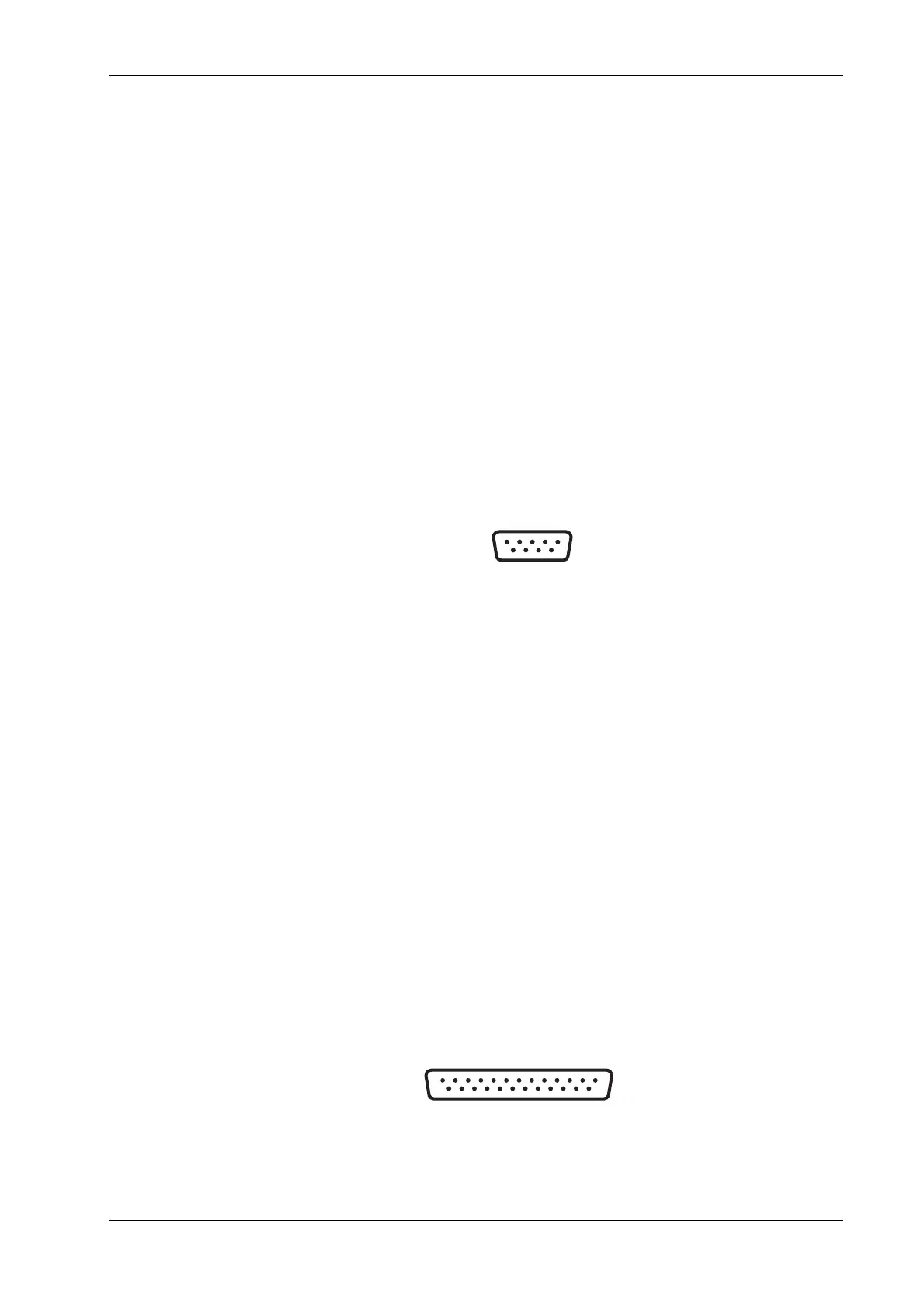
The rear-panel male D-type RS-232 connector is shown in Fig. 2-3.
5
9
1
6
Fig. 2-3 RS-232 connector (viewed from rear of instrument)
The pin-outs for the 9-way RS-232 connector are shown below:
Contact Signal
1 DCD Data carrier detect
2 RXD Receive data
3 TXD Transmit data
4 DTR Data terminal ready
5 SG Signal ground
6 DSR Data set ready
7 RTS Request to send
8 CTS Clear to send
9 RI Ring indicator
The RS-232 interface can be connected to a personal computer’s AT connector using a
null-modem cable. A suitable cable is available from IFR − see Chapter 1, ‘Versions, options and
accessories’.
Auxiliary port connector
The rear-panel 25-way female D-type AUXILIARY PORT connector is shown in Fig. 2-4. This is
used for FSK operation.
13
25
1
14
C0681
Fig. 2-4 25-way AUXILIARY PORT connector