ACCEPTANCE TESTING
7-28 46882/439
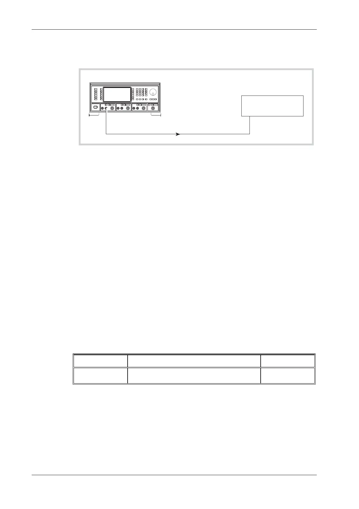
Modulation oscillator distortion and LF output flatness
Test procedure
UUT
INPUTMOD
I/O
C4673
Audio Analyzer
Fig. 7-16 Modulation oscillator distortion test set-up
(1) Connect the test equipment as shown in Fig. 7-16.
(2) On the UUT set source A to:
[MOD ON/OFF] (To enable modulation source)
[FM Mod Freq] 1 kHz
(3) Measure the distortion on the audio analyzer checking that the result is within the
specification shown in Table 7-50.
(4)
Measure the absolute level on the audio analyzer (in dBm) and record this level as a
reference.
(5) Set the UUT mod source to each of the frequencies shown in Table 7-50. Subtract the level
m
easured on the audio analyzer at each frequency from that recorded in (4), checking that
the results are within specification.
(6) Repeat (2) to (5) for source B and, if Option 1 is fitted, source C.
External frequency standard input
Specification
Input levels:
Requires an input of 220 mV RMS to 1.8 V RMS into 1 kΩ.
Input frequencies:
1 MHz or 10 MHz.
Test equipment
Description Minimum specification Example
Signal generator 220 mV to 1.8 V RMS, 1 MHz to 10 MHz IFR 2030 or 2040
series

 Loading...