LOCAL OPERATION
3-18 46882/439
Carrier on/off
The carrier can be switched on or off at any time by means of the [RF ON/OFF] key. This
effectively switches the output on and off, retaining the 50 Ω
output impedance.
RF level selection
You can enter the RF level in the range −137 to +24 dBm (to +20 dBm above 1.2 GHz).
(1) Press [SIG GEN] to show the Sig Gen menu with the current RF level displayed.
(2) Press the [RF Level] soft key to select RF level as the current function.
(3) Enter the required value using the numerical key pad. For voltage terminate using the [μV],
[mV] or [V] key. For logarithmic units terminate using the [dB] key. RF levels in linear and
logarithmic units are selected from the utilities (see ‘Choice of units’ below). If a value
outside the specified range is requested, an error message is displayed and the instrument is
automatically set to the end of the range.
(4) You can then adjust the level either in steps using the [Ø],[×] keys or by using the control
knob for continuous adjustment. The default increment/decrement is 1 dB.
(5) You can check the current amount of offset from the reference level by pressing [TOTAL Δ].
This causes the Total Shift Menu to be displayed.
(6) Pressing [Return Value] returns you to the reference level; pressing [Transfer Value] selects
the currently displayed level as the reference level.
(7) Pressing [SIG GEN] returns you to the Sig Gen menu.
Choice of units
Units may be μV, mV, V or dB. Conversion between dB and the voltage units is carried out by
pressing the appropriate units key; for example, to change dBm to a voltage unit, press any voltage
key for the correct conversion. The choice of Volts EMF, Volts PD and the dB reference is made
by using the RF Level Units Selection Menu.
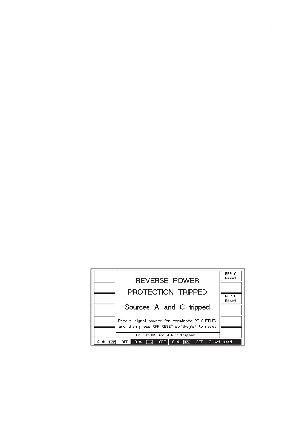
Reverse power protection
Accidental application of power to an individual signal source’s RF OUTPUT socket trips the
reverse power protection circuit (RPP) and a menu similar to that shown in Fig. 3-9 below appears
with a flashing message.
B3473
Fig. 3-9 RPP tripped
Note that the protection circuit may be activated when a source is set to a high level and its RF
OUTPUT socket has no terminating load.