ACCEPTANCE TESTING
7-18 46882/439
(4) On the UUT set source A to:
[FM Devn] 100 [kHz]
[FM ON/OFF]
[UTIL]
[Mod’n Mode]
Press [Down] until “FM external” can be selected
[Select Mode] [EXIT]
[SIG GEN]
[Select Coupling] [Ext DC Coupling] [DCFM Nulling] [EXIT]
(5) On the modulation meter, measure the carrier frequency error displayed in the
FREQUENCY window, checking that the result is within the specification shown in
Table 7-32.
(6
) Repeat (2) to (5) for source B and, if Option 1 is fitted, source C.
External FM frequency response (ALC off, DC coupled)
Test procedure
UUT
50
load
Ω
MOD I/O
RF
OUTPUT
OUTPUT
Temporary
connection
C3501
Function
Generator
Audio
Analyser
DVM
2305
Modulation Meter
RF
INPUT
LF
OUTPUT
INPUT
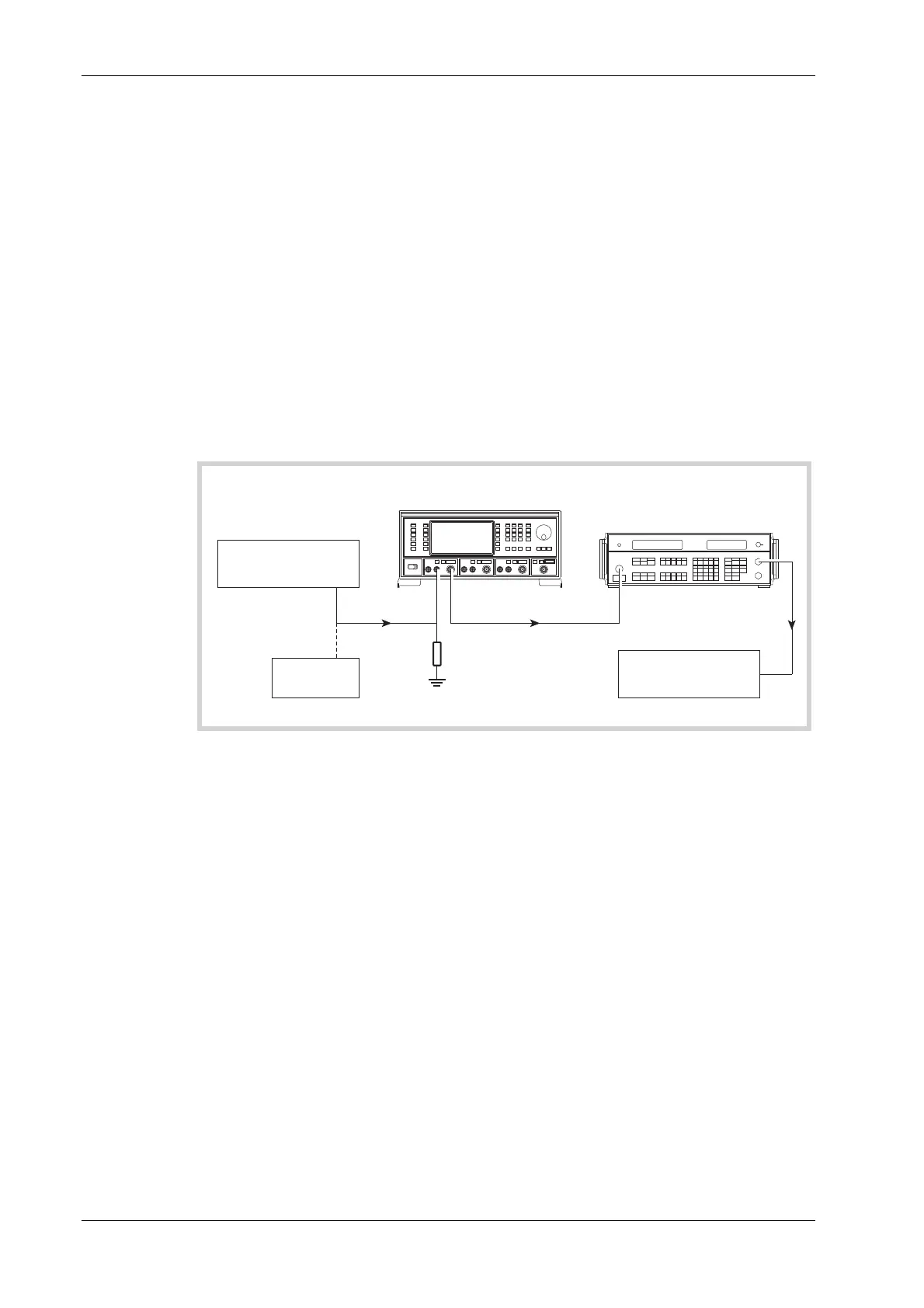
Fig. 7-10 External modulation and modulation distortion test set-up
30 Hz to 100 kHz
(1) Connect the test equipment as shown in Fig. 7-10.
(2) On the UUT set source A to:
[Carrier Freq] 15 [MHz]
[RF Level] 0 [dB]
[FM Devn] 100 [kHz]
[FM ON/OFF]
[UTIL]
[Mod’n Mode]
Press [Down] until “FM external” can be selected
[Select Mode] [EXIT]
[SIG GEN]
[Select Coupling] [Ext DC Coupling] [DCFM Nulling] [EXIT]
(3) Set the function generator to give 1 V RMS, 1 kHz sine wave.
(4) On the modulation meter, select CAL, FM, 10 Hz ⇒ 300 kHz filter.
(5) On the modulation meter, check that the FM reading is between 47.5 kHz and 52.5 kHz,
then set a reference using the relative function.