LOCAL OPERATION
3-34 46882/439
B3457
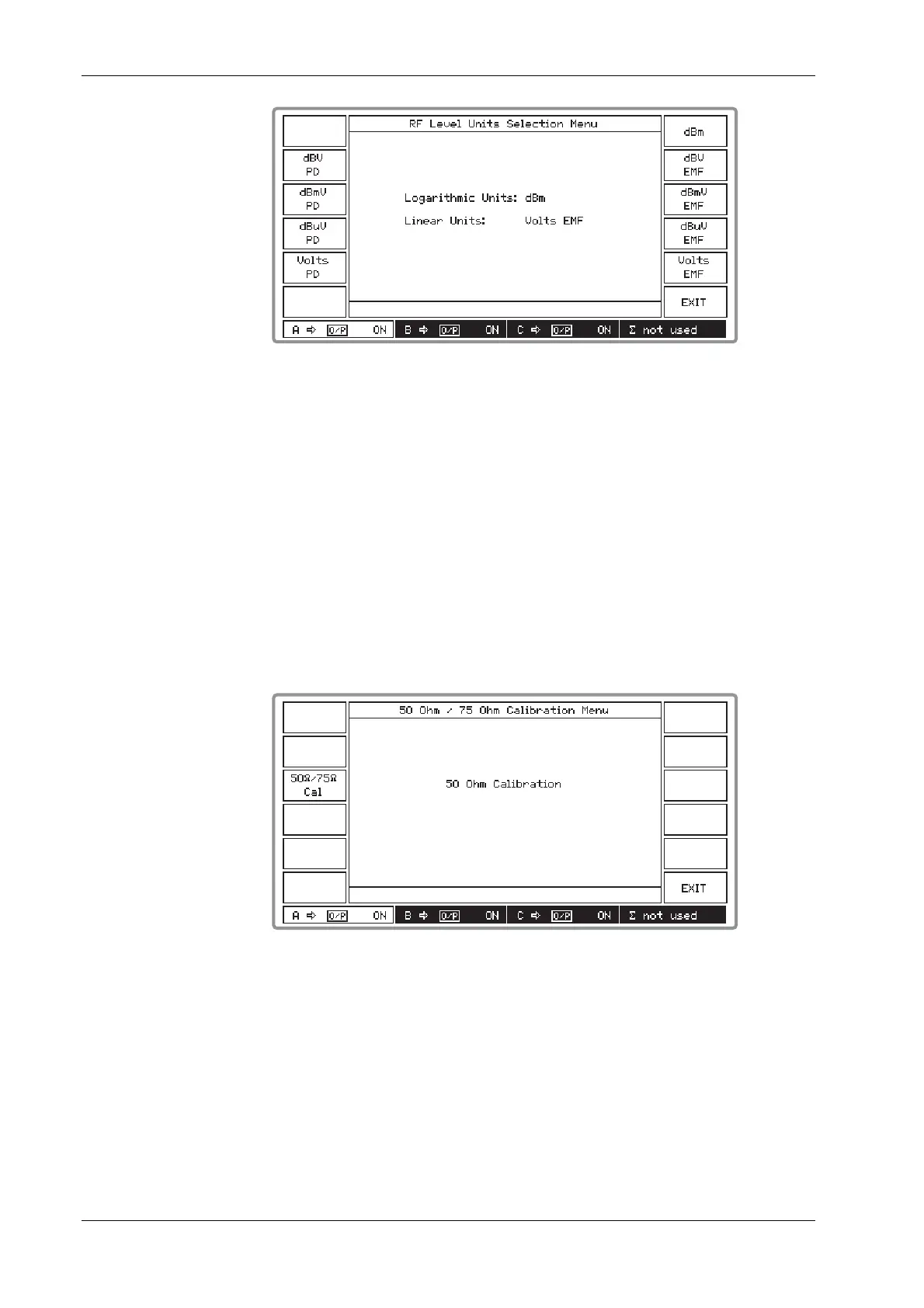
Fig. 3-25 RF level units selection menu
(2) Select between linear and logarithmic units in EMF or PD. Logarithmic units may be
referred to volts (dBV), millivolts (dBmV), microvolts (dBμV) or to 1 millivolt into 50 Ω
(dBm).
(3) Press [EXIT] to return to the Utilities Selection Menu 1.
50 Ω /75 Ω impedance selection (menu 1)
The performance specification of each signal source assumes operation into 50 Ω loads. By
means of this menu in association with a 75 Ω adapter (see data sheet in Chapter 1) you can select
operation into 75 Ω loads whilst maintaining correct voltage calibration. It also enables the
reverse power protection circuit to function correctly. But note that in the event of an overload the
RPP will function but the adapter will NOT be protected. Proceed as follows:
(1) Press [50
Ω/75Ω
Cal] to display the 50 Ohm/75 Ohm Calibration Menu shown in Fig. 3-26
below.
B3458
Fig. 3-26 50 ohm/75 ohm calibration menu
(2) Press [50
Ω/75Ω
Cal] which toggles between 50 Ohm Calibration and 75 Ohm Calibration
as shown by the screen. Note that all RF OUTPUT sockets, including the combiner’s, will
change calibration.
(3) For 75 Ω operation connect a 50 Ω/75 Ω adapter to the front-panel RF OUTPUT socket for
each appropriate signal source. Whenever the impedance is changed, the value of the
displayed level is adjusted (by 5.7 dB) to the level at the output from the adapter.
(4) Press [EXIT] to return to the Utilities Selection Menu 1.