46882/439 4-5
Coupling
Frequency and level coupling
Many measurements are made where it is convenient if the carrier frequencies and RF levels of
signal sources are automatically related to each other. The coupling setup facility allows two or
more signal sources to be coupled together in frequency and/or level. The frequencies can be
coupled with a defined offset value (for example, 10.7 MHz), and can be harmonically related.
The harmonic relationship is useful where a harmonic sampling gate or divider is being tested. RF
levels can be entered in dB. Coupling factors of the B and C sources are always set relative to the
A source.
The frequency coupling is entered in the form:
Frequency (B) = frequency (A)
× N + offset frequency
OR
Frequency (B) = frequency (A)/N
+ offset frequency
where N is an integer between 1 and 9
The B and C sources can be coupled only by entering their value relative to the A source. This
means that if the offset frequency of B relative to A is set as +1 MHz, and C relative to A as
+5 MHz, then C is always offset 4 MHz from B. For this reason, if a measurement requires two
sources to be coupled they should be set as either A and B with C the independent source, or A
and C with B the independent source. Offsets can have either positive or negative values.
Whenever a coupling factor has been set, the signal generator display clearly identifies the
presence of coupling factors in the frequency or level display fields by displaying an icon of the
form
Ö
BC under the frequency/level units to indicate to which sources that parameter is currently
coupled.
Coupling selection
To set the coupling factors proceed as follows:
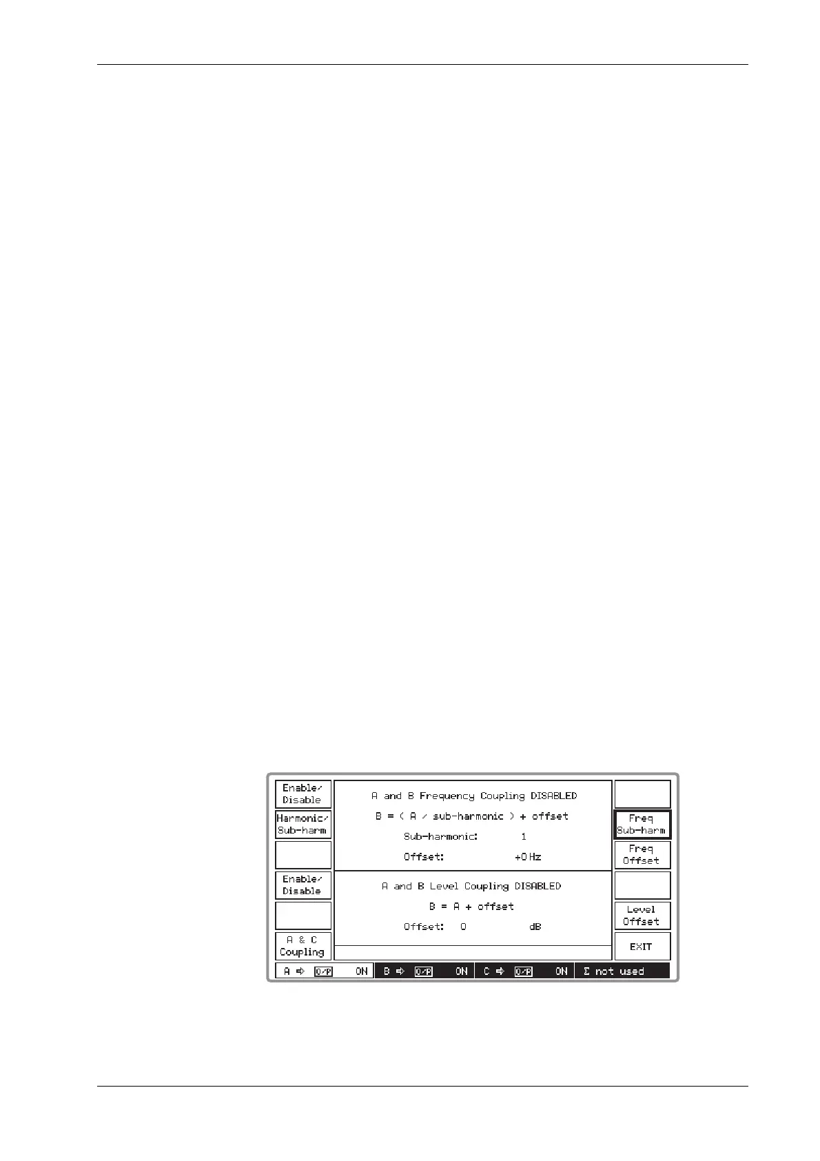
(1) On the Setup Menu press the [Coupling Setup] key to display the Frequency and Level
Coupling menu (see Fig. 4-4 below). The screen is split horizontally into two, with the upper
part displaying the frequency coupling parameters and the lower part displaying the level
coupling parameters.
B3414
Fig. 4-4 Frequency and level coupling menu