APPLICATIONS
46882/439 4-13
(4) The spectral diagram shows the default setting with the A source set to the receiver channel,
the B source (interferer 1) offset higher in frequency than the A source, and the C source
(interferer 2) set to twice that offset. You can reverse the positions of the B and C sources
with respect to A so that the A source is at the higher frequency by entering a negative offset.
The levels of the A, B and C sources are equally offset higher than the A source.
(5) If you wish to continue, press [Accept Appl’n] otherwise press [EXIT] which returns you to
the Applications Selection Menu to enable you to select an alternative test.
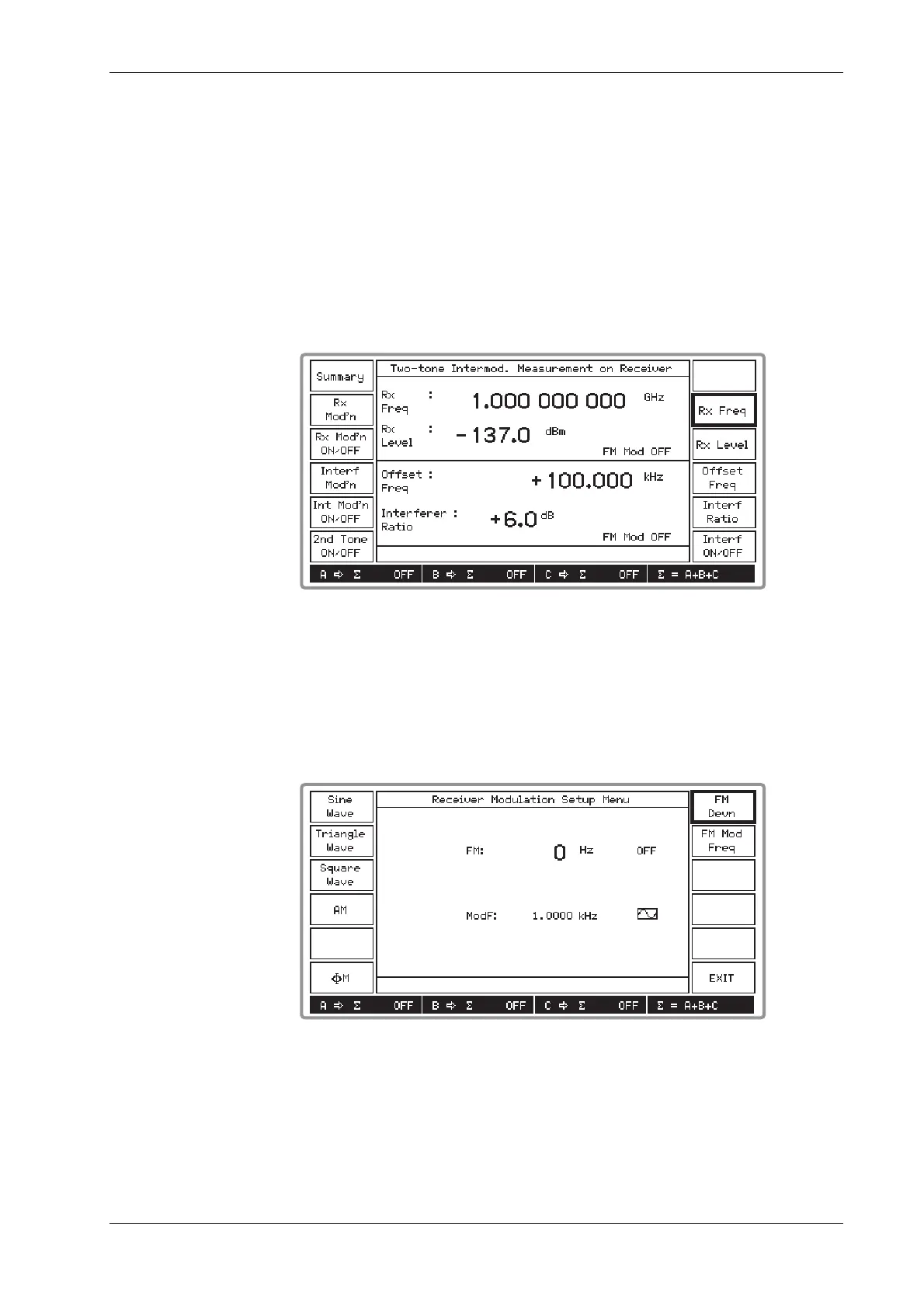
(6) Pressing [Accept Appl’n] displays the screen shown in Fig. 4-15 below. The screen is split
horizontally into two, with the upper part displaying the receiver parameters and the lower
part displaying the interferer parameters. Note that in the signal source field at the bottom of
the screen, the A, B and C sources are shown connected to the combiner by
∑
= A+B+C.
B3399
Fig. 4-15 Two-tone intermod. measurement on receiver: application accepted
(7) Select [Rx Freq] and [Rx Level] to set these parameters for the A source. But note that the
RF level limit is +4 dBm minus the interferer ratio (as shown by Fig. 4-14 above).
(8) If you want to apply modulation to the A source, press the [Rx Mod’n] key to access the
Receiver Modulation Setup Menu shown in Fig. 4-16 below. At the conclusion, press
[EXIT] to return to the previous screen.
B3400
Fig. 4-16 Two-tone intermod. measurement on receiver: modulation setup menu
(9) When the A source is modulated, press [Rx Mod’n ON/OFF] to toggle between the two
states as shown by the screen.
 Loading...