APPLICATIONS
46882/439 4-9
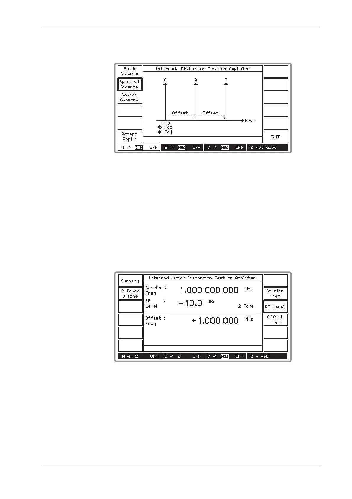
(3) Press [Spectral Diagram] which displays the Intermod. Distortion Test on Amplifier spectral
diagram as shown in Fig. 4-7 below.
B3391
Fig. 4-7 Intermod. distortion test on amplifier spectral diagram
(4) The spectral diagram shows the default setting with the B source offset higher in frequency
than the A source (for a 2-tone test) and the C source offset lower in frequency than the A
source (for a 3-tone test). You can reverse this setting so that the C source is at the higher
frequency by entering a negative offset frequency. Also indicated on the diagram is the
ability for you to additionally modulate and adjust the phase of the carrier of the C source for
a 3-tone test. Also shown is that all signals have the same RF level.
(5) If you wish to continue, press [Accept Appl’n] otherwise press [EXIT] which returns you to
the Applications Selection Menu to enable you to select an alternative test.
(6) Pressing [Accept Appl’n] displays the screen shown in Fig. 4-8 below. The screen is split
horizontally into two, with the upper part displaying the receiver parameters and the lower
part displaying the interferer offset frequency.
B3392
Fig. 4-8 Intermod. distortion test on amplifier: 2-tone selected
(7) Select [Carrier Freq] and [RF Level] to set these parameters. The carrier frequency entered
is that for the A source. The RF level entered is that for all sources, but note that the RF
level limit is +4 dBm.
(8) Select [Offset Freq] to change the equidistant offsets of the interferer B and C sources. You
can reverse the relative positions of the B and C sources by entering a negative offset
frequency.
(9) Select 2 Tone or 3 Tone by pressing [2 Tone/3 Tone] to toggle between the two selections as
shown on the screen.