TEST PROCEDURES
46882/439 7-23
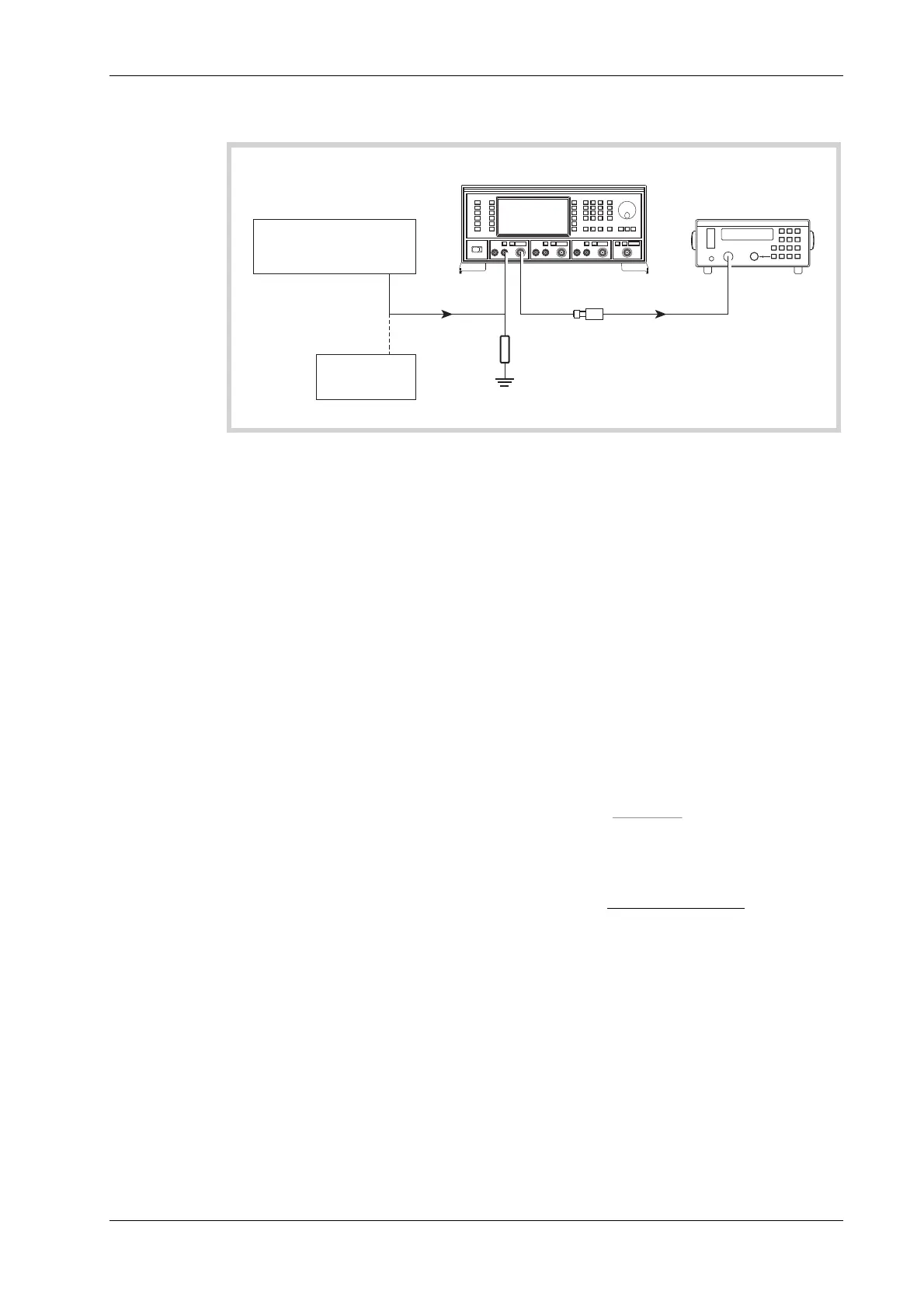
0 Hz (DC)
UUT
6912
Power
Sensor
50
load
Ω
6960B
RF Power Meter
SENSOR
INPUT
MOD I/O
RF
OUTPUT
OUTPUT
Temporary
connection
C3490
Function
Generator
DVM
Fig. 7-11 External AM and distortion test set-up
To measure the AM depth at DC, it will be necessary to use the DC offset facility on the function
generator proceeding as follows:
(9) Connect the test equipment as shown in Fig. 7-11.
(10) Set the UUT RF level to −4 dBm.
(11) Set the function generator to +1.4142 V DC (temporarily connect the function generator
output to the DVM and set this voltage as close as possible to +1.4142 V).
(12) Measure the power on the power meter. P1 _____
(13) Set the function generator to −1.4142 V DC (temporarily connect the function generator
output to the DVM and set this voltage as close as possible to −1.4142 V).
(14) Measure the power on the power meter. P2 _____
(15) Subtract P2 from P1 (= x).
(16) Calculate the modulation depth using the formula:
AM(%) = 1−10
(−x/20)
1+10
(−x/20)
(17) Calculate the 0 Hz response relative to 1 kHz using the following formula, recording the
result in Table 7-43:
20 log
10
Figure recorded in (5)
Figure recorded in (14)
(18) Set the UUT RF level to +6 dBm and repeat (11) to (18) using Table 7-44.
(1
9) Repeat (10) to (18) for source B and, if Option 1 is fitted, source C.

 Loading...