GENERAL INFORMATION
1-2 46882/439
Main features
Operation
Selection of parameters on the screen may involve one or more of the numeric, hard or menu
selection keys or the rotary control knob. Parameters may be set to specific values by numeric key
entry, while values may be varied in steps of any size using the [
Ø][×] keys or altered by
moving the control knob, set to a particular sensitivity.
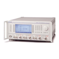
Display
The display is a dot matrix liquid crystal panel, with backlighting. Display contrast and brightness
may be varied to accommodate differing lighting conditions and the setting saved in memory.
Frequency selection
Carrier frequency is either selected directly via the keyboard or remotely via the interfaces.
Frequency resolution is 1 Hz across the complete frequency range of 10 kHz to 2.4 GHz. A series
of carrier frequencies can be stored in non-volatile memory for recall when required.
Output
Peak RF output levels from each signal source of up to +24 dBm can be set up to 1.2 GHz
(+20 dBm up to 2.4 GHz) by direct keyboard entry with a resolution of 0.1 dB down to
−137 dBm. The peak output level from the combiner is +4 dBm up to 1.2 GHz (0 dBm up to
2.4 GHz). RF ON/OFF keys are provided to disable each individual output as well as the
combined output.
A choice of level units is available to the user and provision is made for the conversion of units
(for example, dBm to μV) by a simple keypress.
An electronic trip protects each independent signal source output against reverse power of up to
50 W. This prevents damage to output circuits when RF transmitter or DC power supply is
accidentally applied to an RF OUTPUT connector.
To facilitate testing of receiver squelch systems, an attenuator hold function allows control of the
RF output without introducing RF level drop-outs from the step attenuator.
Modulation
Comprehensive amplitude, frequency and phase modulations are available. Pulse modulation can
be applied to the carrier from an external pulse source. The instrument also produces FSK
modulated outputs. An internal modulation oscillator is provided, having a frequency range of
0.01 Hz to 20 kHz. Sine, triangle and square waveforms are available. The oscillator is capable of
generating one or two modulation tones simultaneously in one modulation channel. A BNC
connector on the front panel offers access to the internal LF signal as well as providing an input
for external modulation signals to be combined with the internal signals. These sources can be
combined to give a number of modulation modes. The pulse modulation can be used in
combination with the other forms of modulation.
The frequency modulation range provides a 1 dB bandwidth of typically 100 kHz and provides
FM deviation of 0 to 100 kHz. AC or DC coupled FM can be selected. Phase modulation is
provided with a 3 dB bandwidth of 10 kHz and deviation range of 0 to 10 radians.
Amplitude modulation with a 1 dB bandwidth of typically 30 kHz and with modulation depths of
up to 99.9% is available with a resolution of 0.1%. Pulse modulation is available as standard with
typical rise and fall times of less than 10 μs and 40 dB on/off ratio.
The instrument also accepts one or two logic level inputs to produce a 2-level or 4-level FSK
modulated output. The required FM deviation is set by keyboard entry.
The external input voltage required for specified modulation is 1 V RMS (1.414 V peak). To
accommodate other signal levels, Automatic Level Control (ALC) can be selected which provides
correctly calibrated modulation for inputs between 0.75 and 1.25 V RMS.
A modulation ON/OFF soft key simplifies the testing of signal-to noise-ratio.

 Loading...