18
HDK-99 1803 VER1 (E)
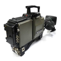
2.1 Camera and Viewfinder
①
Shoulder belt hook
Attaches an optional shoulder belt.
②
VF connector
Connects the VF cable
③
VF CONNECTOR LOCK button
Prevents the VF connector from being disconnected. To disconnect the VF cable, hold
down this button.
④
VF CABLE clamp
Secures the VF cable.
⑤
RET-2/MIC button
The RET-2 switch function or INTERCOM MIC switch function is allocated to this button.
The button selects the function or turns ON/OFF the function.
●
When set to RET-2
The viewnder image is switched from the camera image to RET-2 image while this
button is pressed.
●
When set to INTERCOM MIC
Turns the intercom microphone ON/OFF when the INTERCOM FRONT VR SELECT
switch on the rear of the camera is set to "ENG" or "PROD". The intercom microphone is
turned ON while this button is pressed.
⑥
RET-1 button
Switches the viewnder image from the camera image to RET-1 image. The viewnder
image is switched to the RET-1 image while this button is pressed.
⑦
Breaker
A breaker (8A) for the camera
⑧
MIC CABLE clamp
Secures a microphone cable.
⑨
CAMERA connector
Connects the camera and CCU with a ber cable.
⑩
CAMERA CABLE clamp
Secures the ber cable (9.2mm diameter).
⑪
MEMORY CARD slot
A slot for the memory card (SD card) used to store and recall setup data. When using the
memory card, carefully insert the card in the slot until you hear a clicking sound.
When removing the card, carefully push in the upper part of the inserted card until you hear
a clicking sound. The card will move out, making it possible to remove it.
When not using the memory card, attach the cover to prevent dust from accumulating.
When storing or retrieving data, the access indicator on the side of the the slot is lit. Do not
remove the card if the access indicator is lit.
This could destroy the data on the card, also could destroy the camera data.
Reference:
The functions are allocated
using the menu. Refer to
"5.
CAMERA SETTINGS and
ADJUSTMENT : Menu
Configuration and content"
(P85)
for setting.
Reference:
Refer to
"SAFETY
PRECAUTIONS : Regarding
the Fiber Connector and the
Fiber Optic Cable" (vii)
for
how to handle and secure the
ber cable.