SD1 Series Inverters Function Parameters
-37-
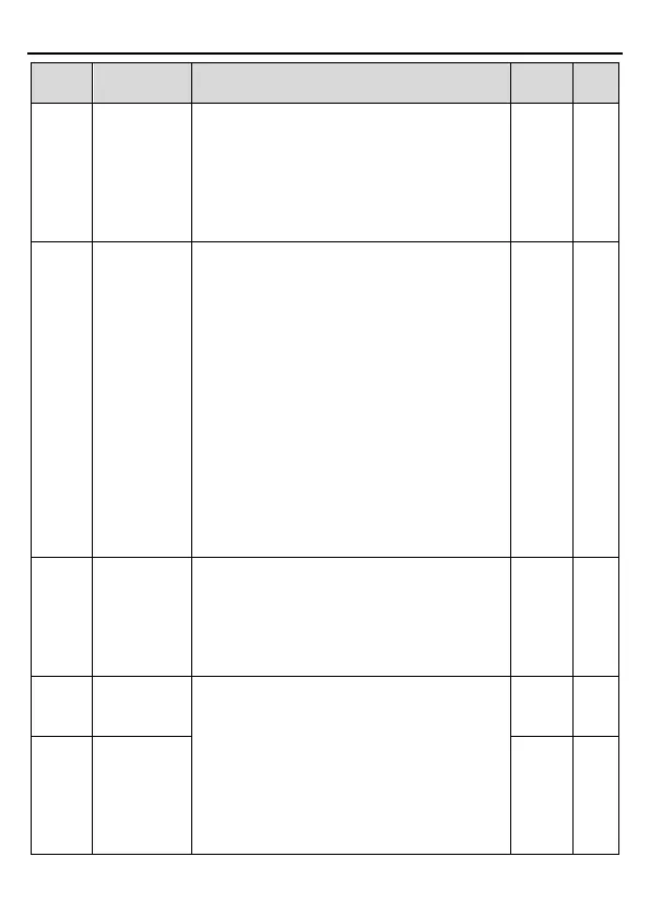
Name Description Default
Modify
P00.08
B frequency
command
reference
selection
0:
Maximum output frequency, 100% of B
frequency setting corresponds to the maximum
output frequency
1: A frequency command, 100% of B frequency
setting corresponds to the maximum output
frequency. Select this setting if it needs to adjust
on the base of A frequency command.
0 ○
P00.09
the setting
source
0: A, the current frequency setting is A frequency
command
1: B, the current frequency setting is B frequency
command
2: A+B, the current frequency setting is A
frequency command + B frequency command
3: A-
B, the current frequency setting is A
frequency command - B frequency command
4: Max.
(A, B): The bigger one between A
frequency command and B frequency is the set
frequency.
5: Min.
(A, B): The lower one between A
frequency command and B frequency is the set
frequency.
Note: The combination manner can be shifted by
0 ○
P00.10
Keypad set
frequency
When A and B frequency commands are
selected as "keypad setting", this parameter will
be the initial value of inverter reference
frequency
Setting range: 0.00 Hz ~P00.03 (the max.
50.00Hz ○
P00.11
Acceleration
time 1
Acceleration time means the time needed for the
inverter to speed up from 0Hz to the maximum
output frequency (P00.03).
Deceleration
time means the time needed if the
inverter speeds down from the maximum output
frequency (P00.03) to 0Hz.
SD1 series inverters
ACC/DEC time which can be selected by P05.
The default ACC/DEC time of the inverter is the
on
○
P00.12
Deceleration
time 1
Depend
on
model
○