SD1 Series Inverters Function Parameters
-66-
Name Description Default Modify
P06.06
Setting range: 0.000~50.000s 0.000s ○
P06.07
Setting range: 0.000~50.000s 0.000s ○
P06.10
RO1 switching
on delay time
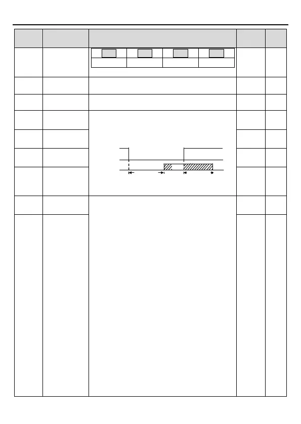
The function code defines the corresponding
delay time of the electrical level change during
the programmable terminal switching on and off.
RO electric level
RO valid
Invalid
Switch on
delay
invalid
Valid
Switch off
delay
Setting range: 0.000~50.000s
0.000s
○
P06.11
RO1 switching
off delay time
0.000s
○
P06.12
RO2 switching
on delay time
0.000s
○
P06.13
off delay time
0.000s
○
P06.14
1: Set frequency
2: Ramp reference frequency
3: Running speed
(relative to twice the motor
synchronous rotational speed)
4: Output current (relative to twice
inverter current)
5: Output current (relative to twice
motor current)
6: Output voltage (relative to 1.5 times the rated
inverter voltage)
7: Output power (relative to twice the rated motor
power)
8: Set torque value (relative to twice
motor torque)
9: Output torque (relative to twice the rated motor
torque)
10: Analog AI1 input value
11: Analog AI2 input value
12: Analog AI3 input value
13: High-speed pulse HDIA input value
14: Value 1 set through Modbus communication
0
○
P06.15
AO2 output
selection
0
○