EasyManuals Logo

IMT 10000 User Manual

IMT 10000
111 pages
To Next Page IconTo Next Page
To Previous Page IconTo Previous Page
Page #65 background imageLoading...
Page #65 background image
Chapter 4 Parts 63
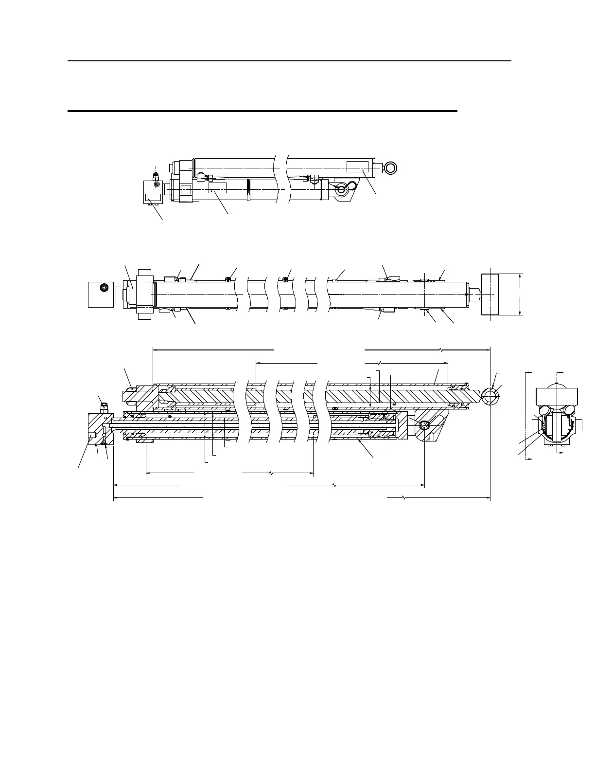
Extension Cylinder Assembly (51723604)
7
7
4
5
5
12
5
3
8
9
1
2
10
3
7
4
6
B
B
2
1
SECTION B-B
STAMP PART # AND REVISION DATE
12
12
4.75"
3/4-10 UNC
0.75" DEEP
140.06" RETRACTED (REF)
102" STROKE
Ø3" BARREL
Ø1.5" ROD
Ø2.5" BORE
Ø2"
Ø1.27"
136.94" RETRACTED (REF)
102" STROKE
Ø3.25" BARREL
Ø1.75" ROD
Ø2.75" BORE
144.69 CLOSED - 348.69 OPEN - 204.00 STROKE
SECTION A-A
5
13
13
NOTES:
1 TEST CYLINDER AT 3500 PSI.
2 TORQUE NUT #3 (1.25-12 UNF) TO 810.7 FT-LB (112 KG-M).
3 PAINT BLACK SEMI-GLOSS.
4 INSTALL HOSE CLAMPS AFTER PAINTING.

Table of Contents

Questions and Answers:

Question and Answer IconNeed help?

Do you have a question about the IMT 10000 and is the answer not in the manual?

IMT 10000 Specifications

General IconGeneral
BrandIMT
Model10000
CategoryConstruction Equipment
LanguageEnglish

Related product manuals