Appendix A
-
128
-
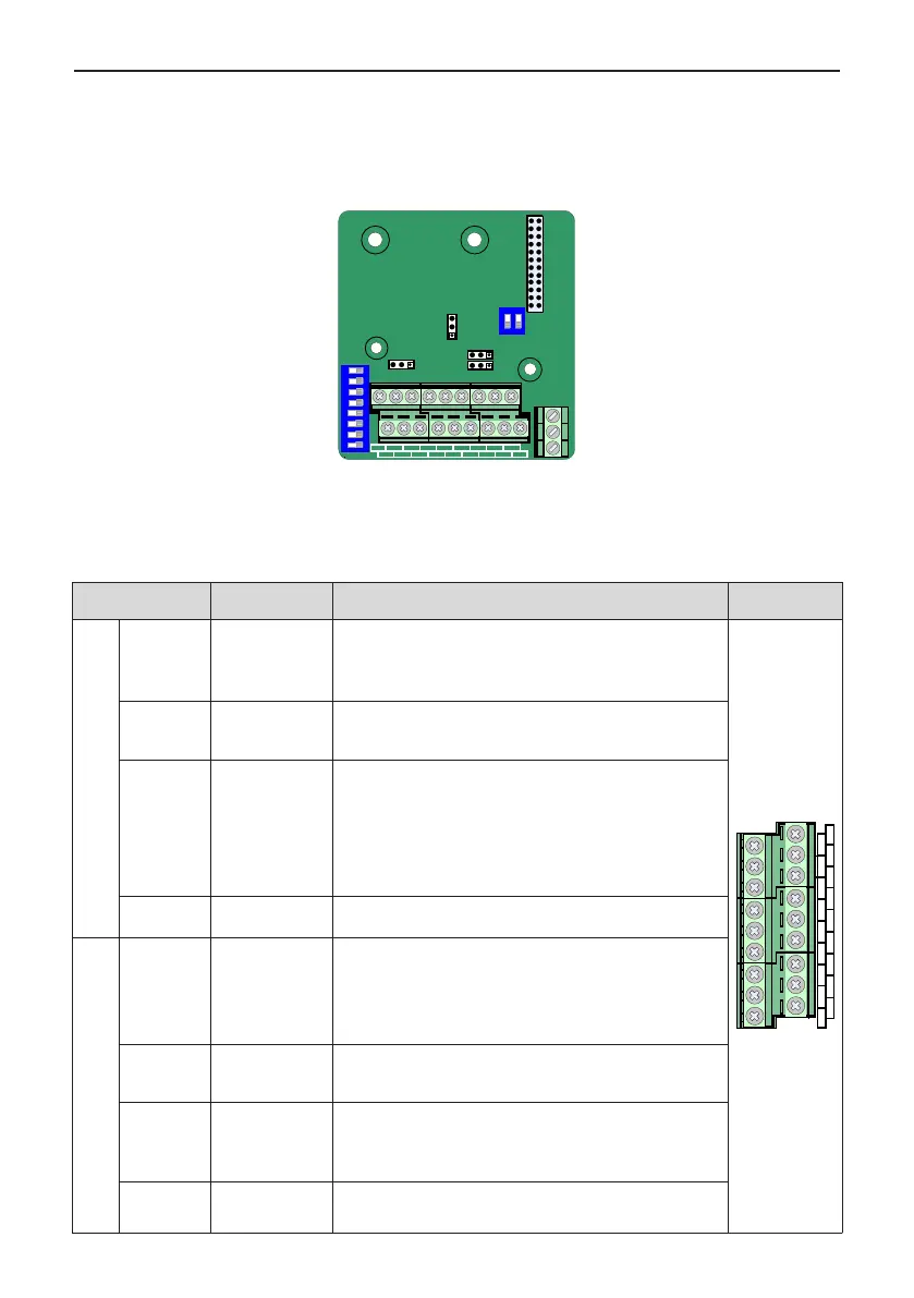
A.3 Layout and Function of Terminals of MD38IO1
MD38IO1 is a multifunctional I/O extension card designed for Inovance AC drives. It has ve digital input (DI)
terminals, an analog input (AI) terminal, a relay output terminal, a digital output (DO) terminal and an analog
output (AO) terminal. It also has the RS485 communication interface and CAN communication interface for
eld bus control.
CN1
J9
ON
1
2
3
4 5 6
7
8
S1
ON
1
2
PA PB PC
S
2
J3
J8
J
7
CN3
CN4
J
4
AI3
AO2 DI6
DI
7 DI8
DI9 DI
10
485+ 485-
PGND
GND
DO2
CME
+24V OP1 COM CANH CANL
Figure A-3 Layout of MD38IO1 terminals
Table A-4 Terminal descriptions of MD38IO1
Terminal Terminal Name Function Description
Terminal
Arrangement
CN4
+24V/COM
External +24VDC
power
supply
1. Provide +24 V power supply to an external unit. Generally
used for power supply for DI/DO terminals and external
sensors.
2. Max. output current: 200 mA
AI3
AO2 DI6
DI7 DI8 DI9 DI10
485+ 485-
PGND
GND
DO2
CME
+24V OP1 COM CANH CANL
OP1
Digital input
power
terminal
1. Connect to +24V by the jumper J8 by default.
2. When applying an external power supply, remove the
jumper J8 and connect the OP1 to the external power supply.
DO2-CME Digital output 2
1. Optically-coupled isolation, dual-polarity open-collector
output
2. Output voltage range: 0 to 24V
3. Output current range: 0 to 50mA
Note that CME1 and COM are internally insulated, but are
shorted by jumper J7 internally. Remove the jumper if you
need to apply an external power to DO2.
CANH/
CANL/COM
Communication
interface
CANlink communication input terminal, isolated input
CN3
AI3-PGND Analog input 3
1. Optically-coupled isolation input, supporting differential
voltage input and temperature detection resistance input
2. Input voltage range: -10 to 10 VDC
3. PT100 and PT1000 temperature sensors
4.Input mode determined by DIP switch S1, multiple functions
not supported simultaneously
AO2-GND Analog output 2
1.Output voltage range: 0 to 10 V
2. Output current range: 0 to 20 mA
3. Output current with resistance range: 0 to 500 Ω
DI6-OP1 to
DI10-OP1
Five digit inputs
1. Optically-coupled isolation compatible with dual-polarity
inputs
2. Input impedance: 2.4 kΩ
3. Voltage range for inputs: 9 to 30 V
485+/485-/
COM
Communication
interface
Modbus-RTU communication input and output terminal,
isolated input

 Loading...