2 System Connection
-
18
-
2
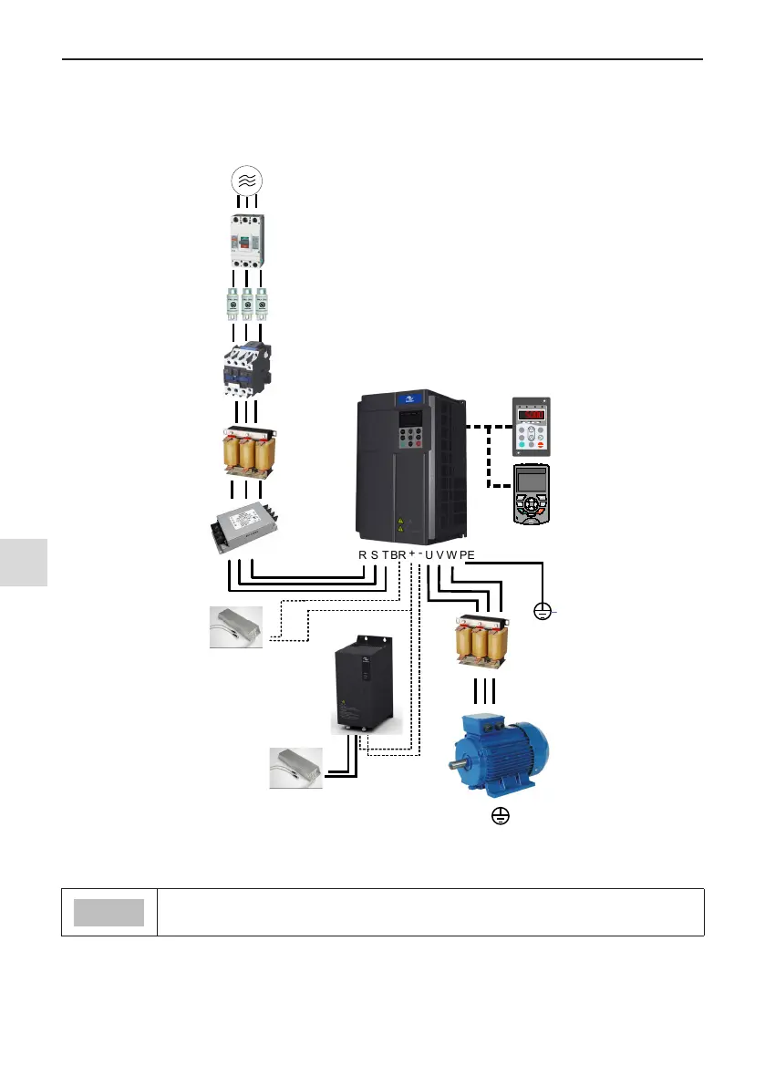
2.1 MD500 System Connection Diagram
When using the drive to drive asynchronous motor, a variety of electrical devices must be installed on both in-
put and output sides to ensure system safety and stability. How to congure the AC drive (three-phase 380 V to
480 V, 0.4 kW and above) to operate with the peripheral devices is shown as below:
Ground
Electromagnetic
contactor
Breaker
Three-phase AC
power supply
Input reactor
Braking
resistor
EMC filter
R S T
P(+)
W
VU
BR
+
-
Ground
+
BR
-
PE
Breaking unit
MDBUN
To prevent electric shock,
AC drive and motor must
be well grounded
Braking
resistor
MD500
External
operating panel
Applicable
motor
Output reactor
MF.K
RUN
STOP
RES
QUICK
PRG
ENTER
RUN
LOCAL/REMOT FED/REV TUNE/TC
RPM
%
A VHz
Fuse
MD32NKE1
MDKE9
MDKE9
Figure 2-1 MD500 Series system composition
● The above gure is just a schematic system connection diagram of MD500 Series AC drive. For
peripherals and options, see "Chapter 8 Specications and Model Selection".

 Loading...